Overview
In this article we discuss the basics of thermocouples, software USB stack setup using the Atmel API without using an external oscillator, and tips for shrinking MCU code on a constrained system.
Contents
Thermocouples
Thermocouples are used to measure temperature and are well suited for high temperature measurements. The physical mechanism of which they rely upon is the thermoelectric effect also known as the seebeck effect. In general the level of accuracy depends upon what type of thermocouple is used but in general expect ±2-3°C from most systems with special limits of error materials reducing this figure.
In a seebeck junction two dissimilar metals such as Chromel and Alumel for type K are joined together directly (typically by welding) to prevent a third metal from being introduced which would change the properties of the junction. When a thermal gradient is applied across this junction it will create a voltage relative to the temerature differential. This voltage is not created at the junction, but across the temperature gradient. It also means that we must have a reference temperature to determine the absolute temperature.
Note that polarity of a thermocouple matters. Improper connection will cause the apparent temperature to decrease instead of increase.
Cold Junction
Since a thermocouple only provides a relative temperature we require a known reference temperature to determine absolute temperature. For this a cold junction is used. Historically this was an ice bath at 0°C. Now, a temperature sensor such as a semiconductor junction is used and then added to the calculated signal using either look-up tables or the polynominal expression presented by NIST.
Thermocouple Equation
Data for the equations can be obtained from NIST ITS-90 Thermocouple Database. The measurements provided were last updated in 1993 and while they are still considered the industry standard those wanting higher precision might want to consider the rational function implementation.
For additional details on thermocouples I recommend review of Texas Instruments SBAA274: A basic guide to thermocouple measurements.
The Microcontroller
| Specification | Value |
|---|---|
| Part Number | ATSAMD11D141 |
| MCU Core | ARM M0+ |
| Package | 24-pin QFN |
| Clock Speed | 48 MHz |
| Memory | 16 KB |
| SRAM | 4 KB |
The microcontroller used is an Atmel SAMD11D14. It has 16 KB of program memory and features an ARM M0+ core. The M0+ core does not offer hardware floating point operations so if we were to utilize floats we would need to use the software libraries which come with a significant memory cost.
Software
The software for this microcontroller was written in C. Communication with the thermocouple amplifier is done with SPI.2
Project Requirements
- USB interface to computer without external oscillator
- SPI interface to the thermocouple interface
- Floating point number output to serial
Setup SPI
| Pin | Function | Type |
|---|---|---|
| PA10 | CS3 | OUTPUT |
| PA11 | MOSI4 | OUTPUT |
| PA14 | MISO5 | INPUT |
| PA15 | CLK6 | OUTPUT |
To setup our SPI interface we create a struct object of type spi_config. We call this config_spi_master. Once created we load our defaults using the function spi_get_config_defaults() and pass in the address of config_spi_master so that it can access it.
Most microcontrollers have multiple functions that are routed by a multiplexer to their respective pin. This means we need to set the SERCOM multiplexer values so that we can correctly use the SPI hardware device with the pins selected. These mux settings are noted below. After setting the pin configuration we set the SPI transfer mode2.
void configure_spi_master(void)
{
	struct spi_config config_spi_master;

	/* Configure, initialize and enable SERCOM SPI module */
	spi_get_config_defaults(&config_spi_master);

	config_spi_master.mux_setting 	= SPI_SIGNAL_MUX_SETTING_I;
	config_spi_master.pinmux_pad0 	= PINMUX_PA14C_SERCOM0_PAD0;
	config_spi_master.pinmux_pad1 	= PINMUX_PA15C_SERCOM0_PAD1;
	config_spi_master.pinmux_pad2 	= PINMUX_PA10C_SERCOM0_PAD2;
	config_spi_master.pinmux_pad3 	= PINMUX_PA11C_SERCOM0_PAD3;
	config_spi_master.transfer_mode = SPI_TRANSFER_MODE_1;

	spi_init(&spi_master_instance, SERCOM0, &config_spi_master);

	spi_enable(&spi_master_instance);
}
Sending SPI Messages
To send a message on the SPI bus we must:
- Set chip select low
- Transfer data
- Set chip select high
If we want to only send data we can use the command spi_write_buffer_wait() and to transceive data we use spi_transceive_buffer_wait()
port_pin_set_output_level(PIN_PA10, 0);
spi_write_buffer_wait(&spi_master_instance, CR0, 2);
port_pin_set_output_level(PIN_PA10, 1);
Where CR0 is a uint8_t array uint8_t CR0[2] = {0x80, 0x80}; to enable automatic sampling mode.
USB Interface
The USB interface stack used was supplied by Atmel as part of their Atmel Advanced Software Framework (ASF)7. In order to get this functioning with our application in crystal-less operation mode we must of course add it from the ASF application to our project, then configure it to enable PLL clock recovery in conf_clocks.h. In my application this is automatically generated in /config/conf_clocks.h. There is also /config/conf_usb.h where we can set vendor ID and name of the USB device if we have them.
To setup USB clock recovery simply enable the clock source to DFLL, and DFLL mode to SYSTEM_CLOCK_DFLL_LOOP_MODE_USB_RECOVERY.
Additional docuementation is available in the ASF USB stack documentation.8
USB Clock Recovery Setup
/* Configure GCLK generator 1 */
#define CONF_CLOCK_GCLK_1_ENABLE                true
#define CONF_CLOCK_GCLK_1_RUN_IN_STANDBY        true
#define CONF_CLOCK_GCLK_1_CLOCK_SOURCE          SYSTEM_CLOCK_SOURCE_DFLL;
#define CONF_CLOCK_GCLK_1_PRESCALER             1
#define CONF_CLOCK_GCLK_1_OUTPUT_ENABLE         false
...
/* SYSTEM_CLOCK_SOURCE_DFLL configuration - Digital Frequency Locked Loop */
#define CONF_CLOCK_DFLL_ENABLE                  true
#define CONF_CLOCK_DFLL_LOOP_MODE               SYSTEM_CLOCK_DFLL_LOOP_MODE_USB_RECOVERY
#define CONF_CLOCK_DFLL_ON_DEMAND               false
USB Application Setup
Once this is configured we add a global variable, and then two functions. These get called by the ASF driver when it is being setup.
/* USB functions required by driver */
static bool my_flag_autorize_cdc_transfert = false;

bool my_callback_cdc_enable(void)
{
	my_flag_autorize_cdc_transfert = true;
	return true;
}

void my_callback_cdc_disable(void)
{
	my_flag_autorize_cdc_transfert = false;
}
In our main() function we initialize everything, start the USB driver, attach to the system, and then we can use it by printing some data to the console.
Sending USB Data
//system initialization
system_init();
irq_initialize_vectors();
cpu_irq_enable();

udc_start();
udc_attach();

//application code
udi_cdc_write_buf(char *, int n_bytes);
Size Optimization
To get the code to fit on the SAMD11 we need to do a few things. First, we cannot use floating point math. This would require invoking the floating point library which will use up our remaining precious memory. Instead we can use integer math operations and use two character arrays temp_integer and temp_decimal then do two printing operations with a decimal in the appropriate position.
Next, we need to disable our debug headers. Since there is so little memory remaining at this point we cannot have debug headers enabled, and we must perform a size optimization. Both of these operations are found by clicking on your programmer and going into build settings.
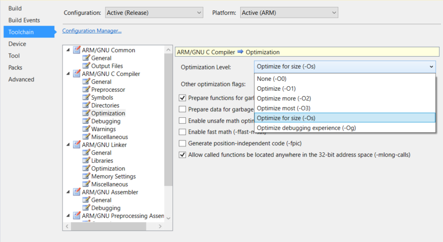
First, we change size optimization to -Os in the compiler settings under optimization.
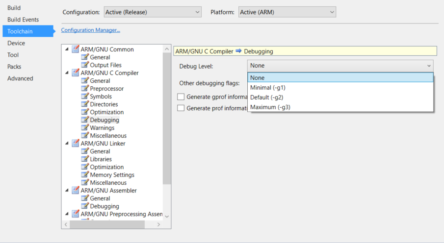
Then we disable our debug headers to get a little bit more memory. To do this we go to debugging under compiler and select none for debug level.
Final Notes

With the size optimization flags turned on, and debug headers removed we manage to squeeze our code on to the memory of the device.
Memory Usage
Program Memory Usage: 15188 bytes 92.7 % Full
Data Memory Usage: 2608 bytes 63.7 % Full
Success!
Direct manipulation of registers and rewriting of drivers can reduce memory usage but comes at a cost of time. Considering the scope of this project the outlined methods are sufficient.
Should functionality be required that exceed the available memory, a cost analysis should be considered to determine if the time required to implement the drivers offers a better return on investment than simply obtaining an MCU with more memory such as the SAMD21 series.