Atmel SAMD51 20x4 LCD Driver
Overview
In this article we discuss developing a custom driver, and provide source code for a 20x4 LCD targeted at the Atmel SAMD51 ARM microcontroller. While this article is targeted at the SAMD51 it is written with abstraction in mind for ease of portability between microcontrollers. Commercial use of this driver is allowed provided you attribute this article with a link and send us an email to let us know it was helpful!
Table of Contents
Background
This driver was created to support a microcontroller application where an output LCD was needed. Since this application is built upon the Atmel ASF4 platform and targets the SAMD51 ARM microcontroller a driver needed to be written. While there are many drivers available this one was written from the ground up in hopes that its added documentation will aid newcomers to writing drivers and code for microcontrollers outside of the common Arduino platform.
You are free to use this driver for commercial applications with attribution and notification (link to this article, and send me an email so I know it was helpful!), however, it is provided without warranty whether express or implied. User assumes all risk.
Hardware
The targeted device for this application is the SAMD51J19A. It is a small 48QFN 120MHz ARM microcontroller from Atmel. While the driver was written on top of the ASF4 platform it uses minimal ASF code to make it functional.
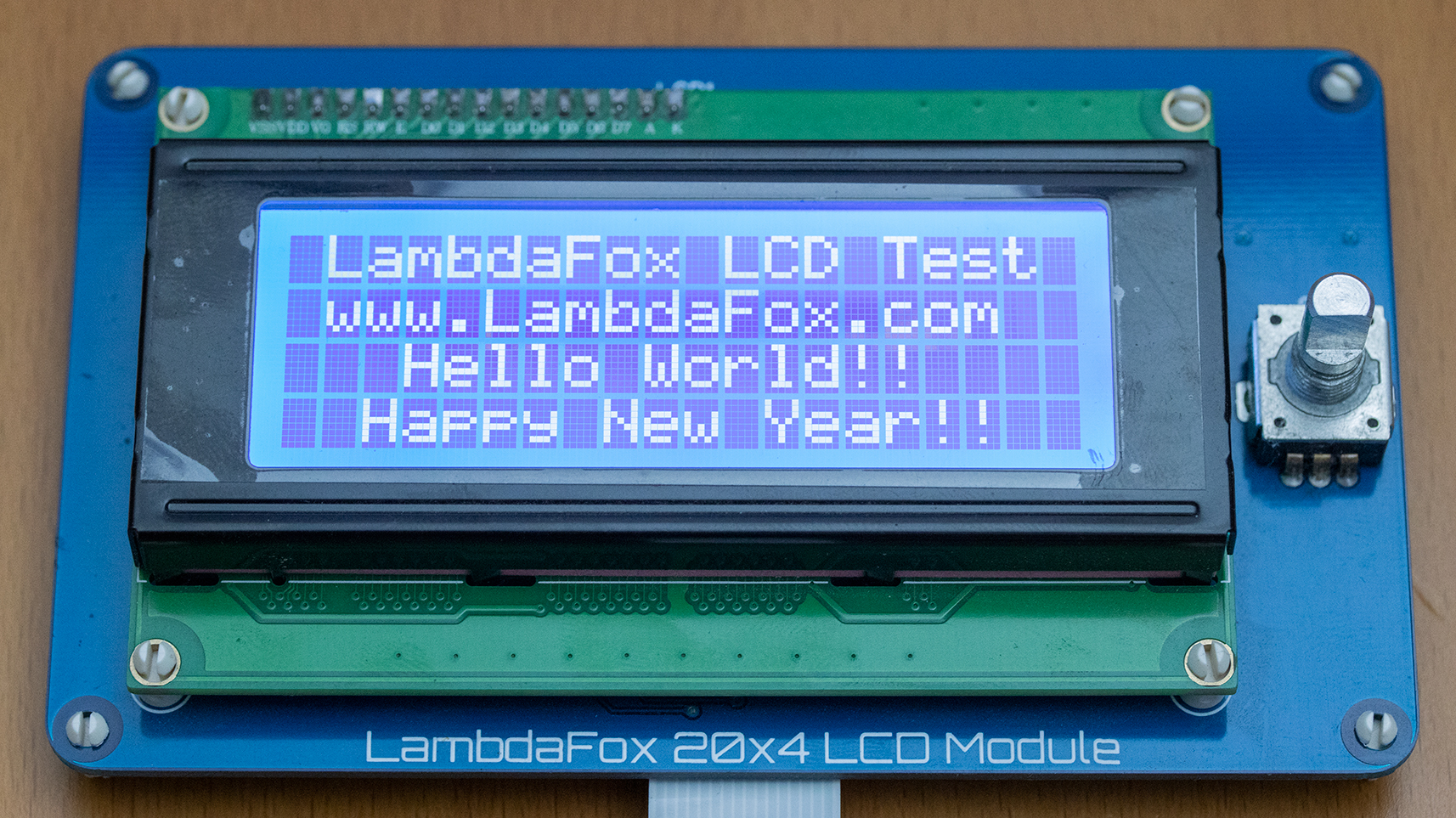
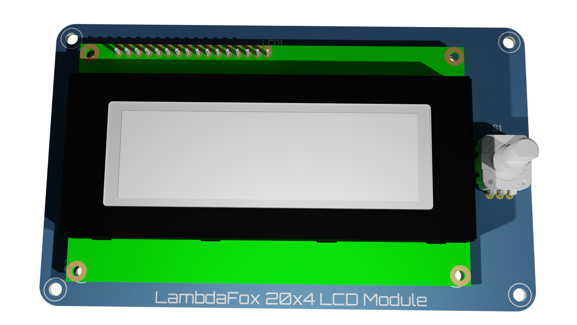
The LCD is our 20x4 LCD module which is connected to our standard flat-flex break-out connector. This LCD uses the standard Hitachi HD44780 compatible interface that most LCDs use these days.
In addition to the application hardware a Seggger J-Link programmer is used to program the MCU, and a logic analyzer was found to be particularly helpful to debug during initial development.
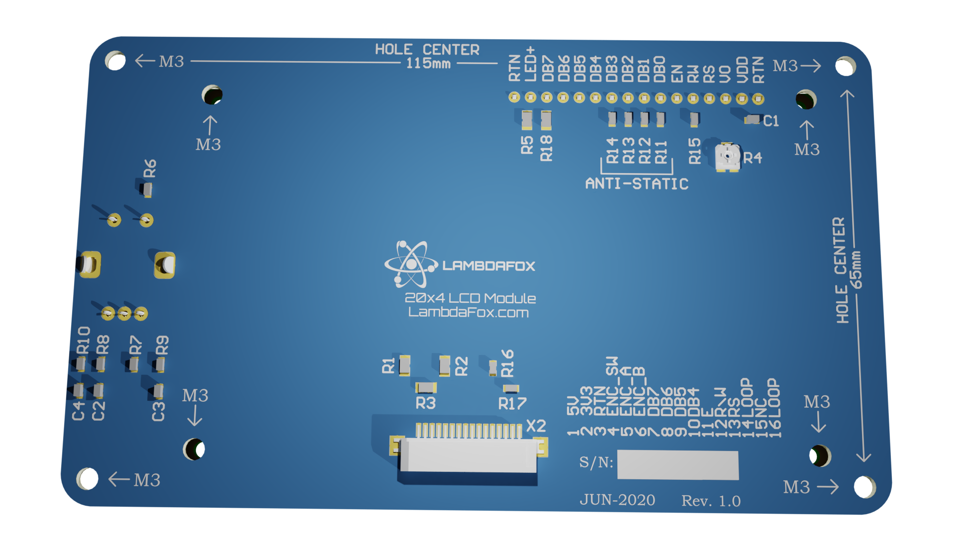
Note: Please contact us if you want to purchase a bare LCD module board as we have spares available. Schematic drawings, and BOM are also available.
Software
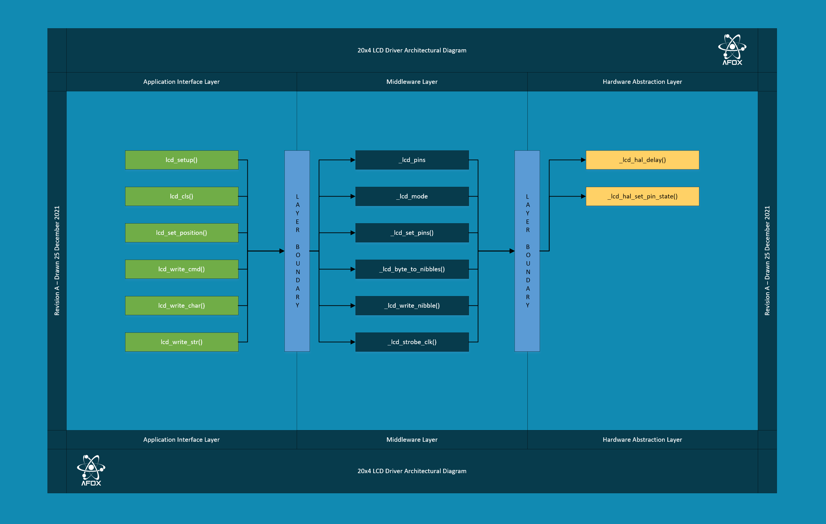
The driver was exclusively developed in C, and documentation added with doxygen tags. It is designed with three layers:
- Application Interface Layer
- Middleware Layer
- Hardware Abstraction Layer
Note: This LCD driver is designed to operate in 4-bit mode only. 8-bit mode is not currently supported. This 4-bit mode has the advantage of requiring fewer connections but is slower. Additionally, pulldown resistors on the LCD DB0->DB4 pins are recommended for better noise immunity.
Application Interface Layer
The application interface layer is the layer that you will use to control the LCD within your program. Simply call lcd_setup() once to initialze the LCD, then you can call the other methods as needed.
Note: While the other methods are callable, you are advised to not to use them after you setup the HAL to support your hardware.
The driver has been designed to accept a single character lcd_write_char() or a string lcd_write_str(). The driver will automatically increment text as it writes, and supports both newline characters /n and carriage returns /r within text. To reset the position to zero you can use either the clear screen command lcd_cls() or the set position command lcd_set_position().
Initialization Example
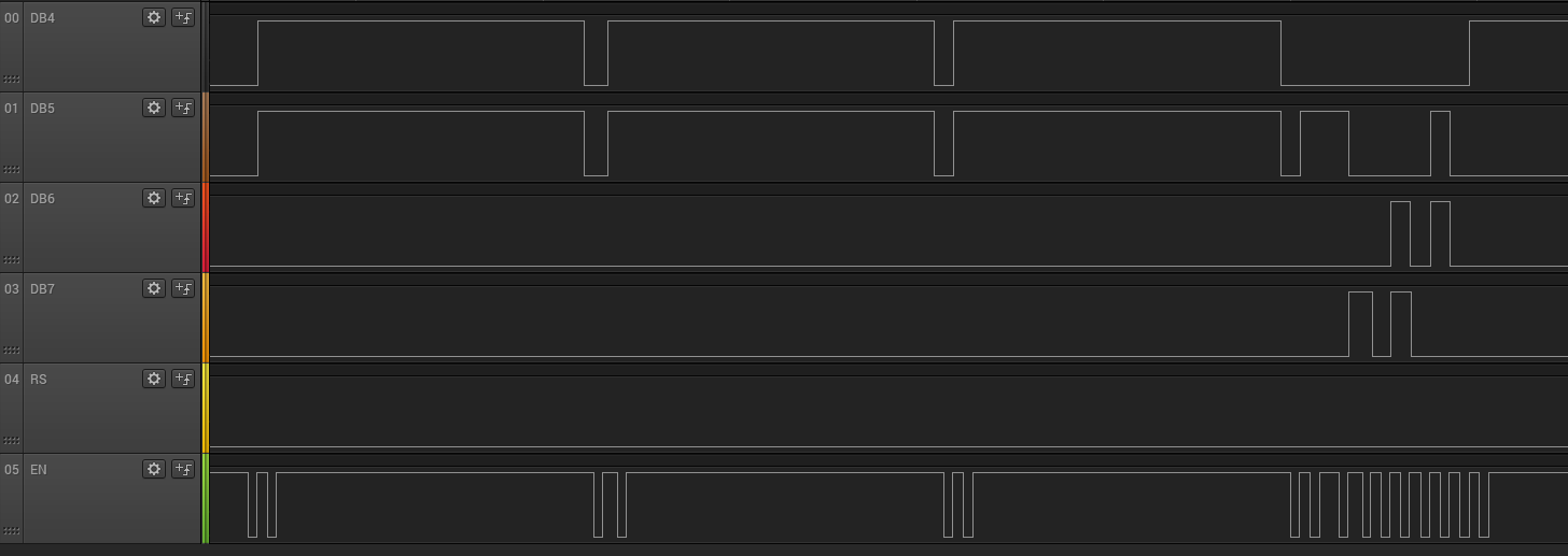
If you setup everything and connect some logic probes it should look something like this diagram if done properly.
Middleware Layer
The middleware layer are helper functions that perform actions between the application interface layer and the hardware abstraction layer. These include methods that strobe the LCD clock, split a byte into nibbles for the 4-bit interface, and so forth.
Hardware Abstraction Layer
The hardware abstraction layer (HAL) is the layer that interfaces the LCD driver to your particular device. This is the layer that you will need to rewrite for each device. The layering scheme helps support minimizing redesign efforts when transitioning to other hardware.
The HAL has only two methods _lcd_hal_delay() which is the interface to the microcontrollers delay function, and _lcd_hal_set_pin_state() which is the interface to the GPIO.
HAL Delay Method
The delay method is very simple, and simply takes in a delay duration in microseconds. This is then passed to the microcontroller’s method of delay.
/*
* @brief Abstraction to hook another method
* of delay into the LCD driver.
* Use this with a counter to remove blocking
* for RTOS or high speed applications
*
* @param duration Duration to delay in microseconds
*/
void _lcd_hal_delay(int duration){
	delay_us(duration);
}
In your application you will need to replace delay_us() since this method is part of Atmel’s ASF framework. Simply replace it with an equivalent delay microsecond function that can accept an integer of duration.
#define _LCD_DELAY_CLK 400
#define _LCD_DELAY_NIBBLE 400
#define _LCD_DELAY_CMD 400
#define _LCD_DELAY_CHAR 400
#define _LCD_DELAY_STARTUP 40000
The specific delay durations are defined in the header to allow easy customization to suite your hardware. The values can be determined from the hardware datasheet but the values used were experimentally determined for best reliability.
Note: This driver is written with blocking delays. If your application uses a real-time OS (RTOS), or you need higher speed consider replacing this function with a timer or non-blocking method then re-writing some of the driver to form an LCD task.
Hint: If your microcontroller does not have a delay function easily available, look for a method to use the NOP command. In ARM microcontrollers it uses 1 clock cycle per NOP therefore you can calculate the delay time if you know your clock rate.
GPIO Interface Method
The second part of the HAL layer is the GPIO interface method. This is how the driver sets the state of the GPIO pins.
/*
* @brief Hardware abstraction layer to write to individual pins
*  the individual cases will need to be replaced with a function
\*  that can take a int \[1|0] and write it to the wired pin.
*
* @param pin Enum (_lcd_pins)
*
* @param state 1 is HIGH and 0 is LOW
*
*/
void _lcd_hal_set_pin_state(int pin, int state){
	switch(pin){
		case(_LCD_DB4):
			gpio_set_pin_level(LCD_DB4, state);
			break;
		case(_LCD_DB5):
			gpio_set_pin_level(LCD_DB5, state);
			break;
		case(_LCD_DB6):
			gpio_set_pin_level(LCD_DB6, state);
			break;
		case(_LCD_DB7):
			gpio_set_pin_level(LCD_DB7, state);
			break;
		case(_LCD_RS):
			gpio_set_pin_level(LCD_RS, state);
			break;
		case(_LCD_EN):
			gpio_set_pin_level(LCD_EN, state);
			break;
	}
}
This design uses a switch case to switch between the pins. An Enum was used for ease of use with the design. In the case of the Atmel ASF framework the method to set the state of a pin is gpio_set_pin_level(). For other microcontrollers this is the part that will need to be replaced.
To replace this you simply need a function that will accept a value of 1 or 0 corresponding to the state variable for how your system is wired.
Note: The values LCD_DBx through LCD_EN are #defines created by the ASF tools. These would be the specific pinout to wire the LCD to. Do not include these in your application, only pass the state variable to your custom pin method and assignment.
Source Code
Note: While this code has been initially tested it has not been put full a through regression and unit test. It is possible that bugs exist with it. No warranty expressed or implied shall be provided. User assumes all risk with use.
License Terms
This code may be used for commerical use, however, under all use cases it must maintain attribution to LambdaFox, and include a link to our website or this article. Additionally, I ask that you email us to let us know you used it so we can stay motivated to spend more time on projects like this.
Header File
/************************************************************************/
/* 20x4 LCD Driver for Atmel SAMD51										*/
/* Creator: LambdaFox                                                   */
/* License Terms: Commercial Use Permitted, Must Attribute and Notify	*/
/*				-> see website for full license terms <-				*/
/* Website: http://www.LambdaFox.com									*/
/* File: lcd.h															*/
/* Revision: A															*/
/* Date: 25 December 2021												*/
/************************************************************************/

#ifndef _LCD_H
#define _LCD_H

#define _LCD_DELAY_CLK 400
#define _LCD_DELAY_NIBBLE 400
#define _LCD_DELAY_CMD 400
#define _LCD_DELAY_CHAR 400
#define _LCD_DELAY_STARTUP 40000

typedef struct Position{
	int column;
	int row;
	} Position_t;

enum _lcd_pins{_LCD_DB4, _LCD_DB5, _LCD_DB6, _LCD_DB7, _LCD_RS, _LCD_EN};

enum _lcd_mode{_LCD_CMD = 0, _LCD_CHAR = 1};

void lcd_setup();

void lcd_cls();

void _lcd_set_pins(int D4, int D5, int D6, int D7, int RS);

void _lcd_byte_to_nibbles(unsigned char char_byte, int mode);

void lcd_write_cmd(unsigned char command);

void lcd_write_char(unsigned char character);

void _lcd_write_nibble(unsigned char nibble, int mode);

void _lcd_hal_set_pin_state(int pin, int state);

void _lcd_strobe_clk();

void _lcd_hal_delay(int duration);

#endif
C File
/************************************************************************/
/* 20x4 LCD Driver for Atmel SAMD51										*/
/* Creator: LambdaFox                                                   */
/* License Terms: Commercial Use Permitted, Must Attribute and Notify	*/
/*				-> see website for full license terms <-				*/
/* Website: http://www.LambdaFox.com									*/
/* File: lcd.c															*/
/* Revision: A															*/
/* Date: 25 December 2021												*/
/************************************************************************/

#include "lcd.h"

#include "atmel_start_pins.h"				//include only when using Atmel ASF4


Position_t lcd_position = {0, 0};			//initialize address to zero


/*
* @brief LCD setup command. Run command to initialize LCD.
*/
void lcd_setup(){
	_lcd_hal_delay(_LCD_DELAY_STARTUP);		//initial power-up delay

	for(int x = 0; x < 3; x++){				//wake up display

		lcd_write_cmd(0x03);
	}

	lcd_write_cmd(0x02);					//return cursor home


	lcd_write_cmd(0x28);					//4-Bit Mode, 2 Line

	lcd_write_cmd(0x0C);					//display ON/OFF control

	lcd_write_cmd(0x6);						//entry mode set


	lcd_cls();								//clear screen

}

/*
* @brief Clear LCD screen
*/
void lcd_cls(){
	lcd_write_cmd(0x01);					//clear screen data

	lcd_write_cmd(0x80);					//cursor to zero

	lcd_position.column	= 0;				//reset position memory

	lcd_position.row	= 0;
}

void lcd_set_position(int row, int column){

	while(column > 20){						//wrapping support

		column = column - 20;
		row = row + 1;
	}

	switch(row){							//display cursor starts one

											//column before the write

		case 0:
			lcd_write_cmd(0x80 + column - 1);
			break;
		case 1:
			lcd_write_cmd(0xC0 + column - 1);
			break;
		case 2:
			lcd_write_cmd(0x94 + column - 1);
			break;
		case 3:
			lcd_write_cmd(0xD4 + column - 1);
			break;
	}
	lcd_position.row	= row;
	lcd_position.column = column;
}

/*
* @brief pin writing method
*
* @param D4 state to write to LCD DB4
*
* @param D5 state to write to LCD DB5
*
* @param D6 state to write to LCD DB6
*
* @param D7 state to write to LCD DB7
*
* @param RS state to write to LCD RS
*/
void _lcd_set_pins(int D4, int D5, int D6, int D7, int RS){
	_lcd_hal_set_pin_state(_LCD_DB4, D4);
	_lcd_hal_set_pin_state(_LCD_DB5, D5);
	_lcd_hal_set_pin_state(_LCD_DB6, D6);
	_lcd_hal_set_pin_state(_LCD_DB7, D7);
	_lcd_hal_set_pin_state(_LCD_RS,  RS);
	_lcd_strobe_clk();
}


/*
* @brief Convert input byte to two nibbles. Send MSB first.
*
* @param char_byte Input byte
*
* @param mode _lcd_mode._LCD_CMD or _LCD_CHAR
*/
void _lcd_byte_to_nibbles(unsigned char char_byte, int mode){
	_lcd_write_nibble(char_byte >> 4, mode);	//send MSB first

	_lcd_hal_delay(_LCD_DELAY_NIBBLE);
	_lcd_write_nibble(char_byte, mode);			//send LSB next

	_lcd_hal_delay(_LCD_DELAY_NIBBLE);
}


/*
* @brief Write a command to the LCD
*
* @param command Single byte command to send
*/
void lcd_write_cmd(unsigned char command){
	_lcd_hal_delay(_LCD_DELAY_CMD);
	_lcd_byte_to_nibbles(command, _LCD_CMD);
}

/*
* @brief Write a single character to the LCD
*
* @param character Single byte character
*/
void lcd_write_char(unsigned char character){
	if((character == '\0')){					//ignore end of line

	}
	else if(character == '\r'){
		lcd_position.column = 0;
		lcd_set_position(lcd_position.row, lcd_position.column);
	}
	else if (character == '\n'){				//next line

		lcd_position.row	= lcd_position.row + 1;
		lcd_position.column = 0;
		lcd_set_position(lcd_position.row, lcd_position.column);
	}
	else{										//valid ascii chars

		lcd_position.column = lcd_position.column + 1;
		lcd_set_position(lcd_position.row, lcd_position.column);
		_lcd_hal_delay(_LCD_DELAY_CHAR);
		_lcd_byte_to_nibbles(character, _LCD_CHAR);
	}
}

/*
* @brief Write a string to the LCD display
*
* @param lcd_str String or character array
*/
void lcd_write_str(char *lcd_str){
	int i = 0;
	while(lcd_str[i] != '\0'){
		lcd_write_char(lcd_str[i]);
		i ++;
	}
}

/*
* @brief Write 4-bit nibble to LCD
*
* @param nibble 4 bit value to write to the LCD
*
* @param mode
*/
void _lcd_write_nibble(unsigned char nibble, int mode){
	int bit_DB4 = 0;
	int bit_DB5 = 0;
	int bit_DB6 = 0;
	int bit_DB7 = 0;

	//separate out bits (nibble >> X)

	//ensure only one bit is sent (& 0x01)

	bit_DB4 = (nibble >> 0) & 0x01;
	bit_DB5 = (nibble >> 1) & 0x01;
	bit_DB6 = (nibble >> 2) & 0x01;
	bit_DB7 = (nibble >> 3) & 0x01;

	_lcd_set_pins(bit_DB4, bit_DB5, bit_DB6, bit_DB7, mode);
}


/*
* @brief Hardware abstraction layer to write to individual pins
*  the individual cases will need to be replaced with a function
\*  that can take a int \[1|0] and write it to the wired pin.
*
* @param pin Enum (_lcd_pins)
*
* @param state 1 is HIGH and 0 is LOW
*/
void _lcd_hal_set_pin_state(int pin, int state){
	switch(pin){
		case(_LCD_DB4):
			gpio_set_pin_level(LCD_DB4, state);
			break;
		case(_LCD_DB5):
			gpio_set_pin_level(LCD_DB5, state);
			break;
		case(_LCD_DB6):
			gpio_set_pin_level(LCD_DB6, state);
			break;
		case(_LCD_DB7):
			gpio_set_pin_level(LCD_DB7, state);
			break;
		case(_LCD_RS):
			gpio_set_pin_level(LCD_RS, state);
			break;
		case(_LCD_EN):
			gpio_set_pin_level(LCD_EN, state);
			break;
	}
}

/*
* @brief Strobe the EN pin of the LCD to
* clock in the next bit of data
*/
void _lcd_strobe_clk(){
	_lcd_hal_set_pin_state(_LCD_EN, 1);
	_lcd_hal_delay(_LCD_DELAY_CLK);
	_lcd_hal_set_pin_state(_LCD_EN, 0);
	_lcd_hal_delay(_LCD_DELAY_CLK);
}

/*
* @brief Abstraction to hook another method
* of delay into the LCD driver.
* Use this with a counter to remove blocking
* for RTOS or high speed applications
*
* @param duration Duration to delay in microseconds
*/
void _lcd_hal_delay(int duration){
	delay_us(duration);
}