Overview
In this article we discuss the modeling of a wound toroid using Solidworks. This method uses surfaces and is a very fast method of creating a helical path around a curve. This method could also be used for generating complex wrapped helix shapes around objects, too.
Table of Contents
Background
When you develop electronics sometimes manufacturers will not have a 3D model available. Additionally, when you deal with high-reliability projects often times you will need a highly accurate model for electromagnetic and mechanical simulations. Modeling of the this toroid is suitable for both of these applications.
While this tutorial is focused on a single-layer winding, it can be extended to support multiple windings by offsetting from the initial offset core geoemetry and repeating the steps.
Note
This article is applicable to Solidworks. While other CAD programs can be used to do similar things their steps will likely differ.
The steps to model the wound toroid:
- Model Toroid Geometry
- Offset Toroid Surface
- Surface Sweep
- Intersection Curve
- Sweep Wire Profile Along Curve
- Trim Surface
- Extend Lead
Modeling Toroid
The toroid geometry in this example is modeled off of the Fair-Rite 594000301 core. To create the core geometry the revolve command is used based on the cross-section of the core geometry. You could just as easily create the geometry with an extruded cylinder shape but this method allows for finer control over the profile when warranted.
Revolve Profile
Note that the line in the center of the toroid is used as the rotational point. Your exact geometry will vary. For best results consult the manufacturers datasheet, however, note that most manufacturers do not provide comprehensive mechanical dimensions. Given this, some values such as the radius will need to be guessed, or manually measured depending on level of accuracy needed.
Note
When creating highly-realistic models don’t forget to add tolerances in the physical geomtry as the tolerances can quickly add as a source of simulation error.
Resultant Revolve

This is the resultant revolved shape. Note that an appearance has been applied to the body.
Adding Fillets
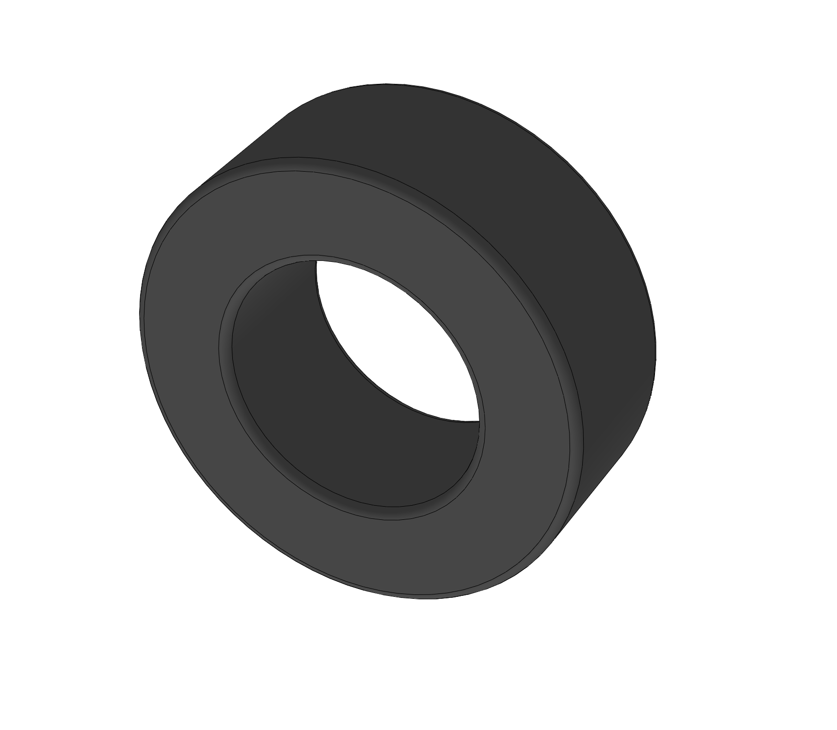
Adding a small fillet to the edges as measured on the physical device. Note that most cores have a radius on the edge. Without this radius damage to the winding insulation would likely result. The radius can be measured with a radius gauge or visually estimated for less critical applications.
Generating the Winding
To generate the winding path we must first create a curve that is then used as the reference for the surface command. Note that the Helix command in Solidworks does not support wrapping around a profile so we must use the surface sweep method which is then the reference path for later operations. We then generate our final path by using the intersection curves on an offset surface.
Create Offset Surface

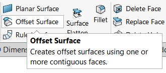
Once the base toroid has been completed we start our winding curve process by generating the offset surface. This surface should be offset based on the dimensions of the winding. In this example 0.5mm winding diameter is used and the offset is also 0.5mm. This command can be found in the Surfaces tab.
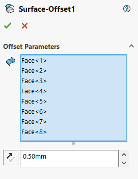
Simply select all the surfaces of the toroid, offset the surface, and then it should looks something like this result when completed. This will then be used as the reference wrap position for the coil.
Note
We will be hiding this offset surface to make the next steps clearer.
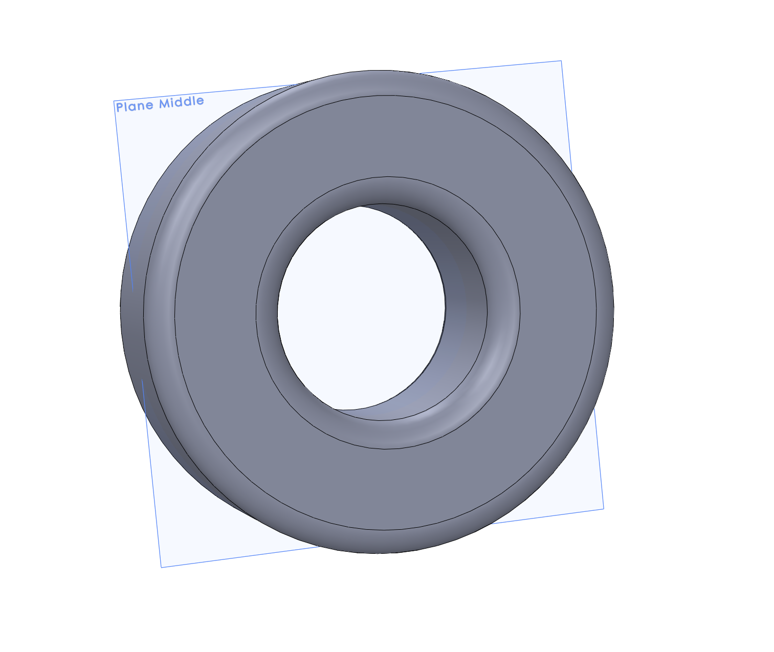
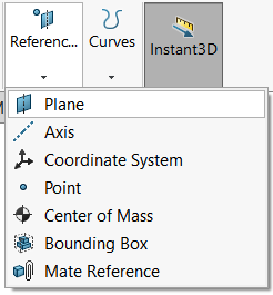
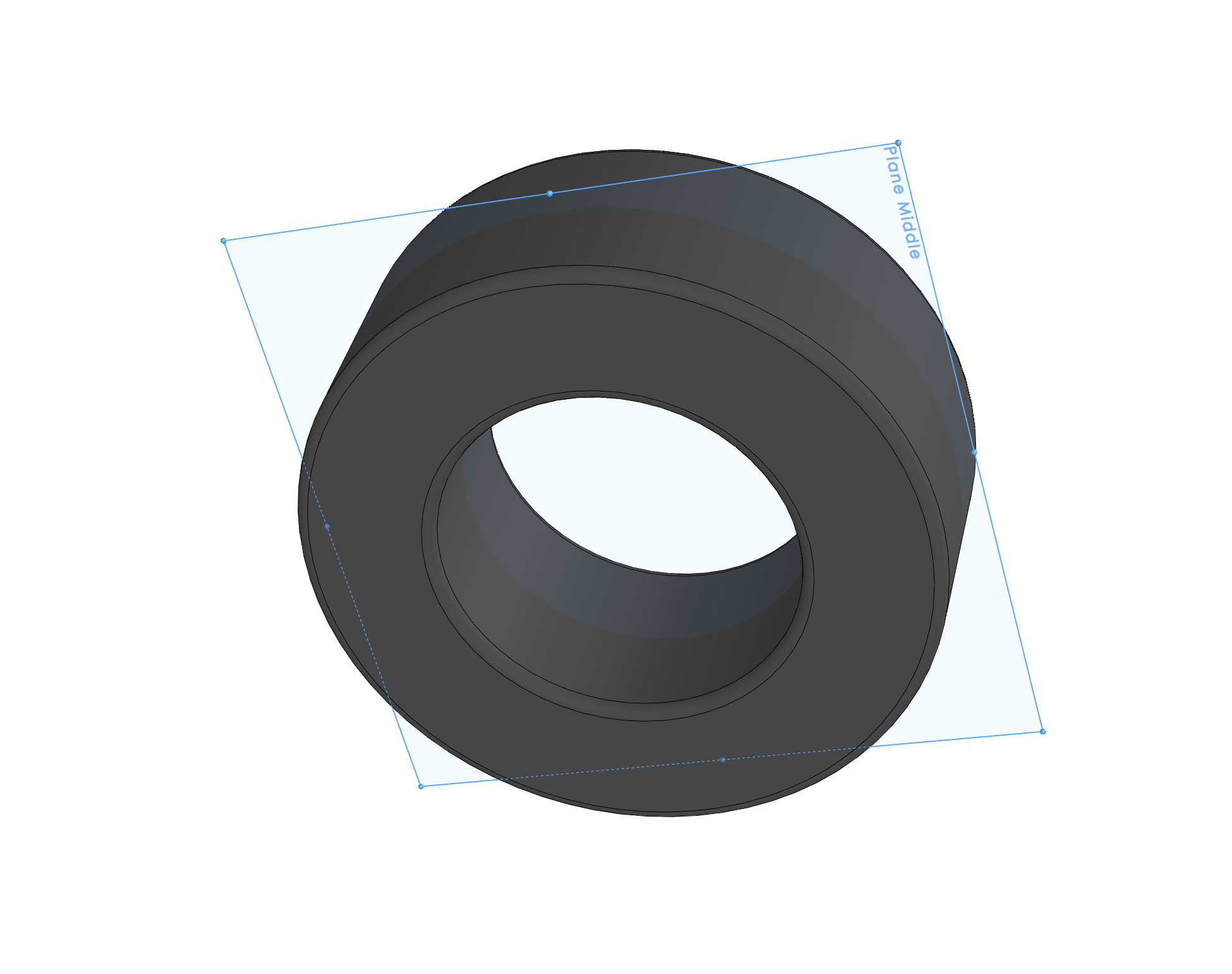
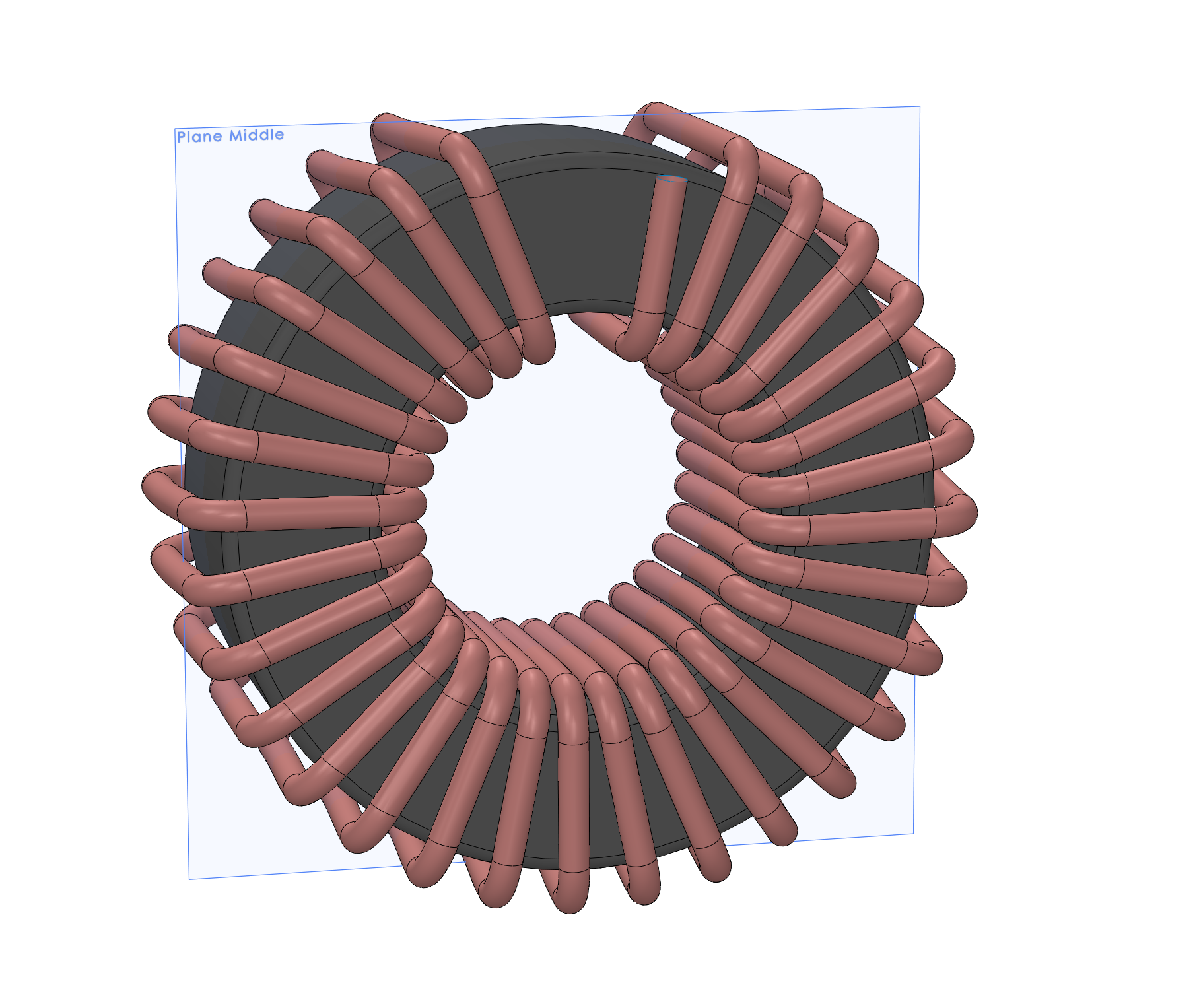
Create Mid-Toroid Plane
First we create a mid-toroid plane to slice the geometry. This is done by going to features, reference geometry, then plane.
Simple select one side of the toroid as reference one, and the other side as reference two. This will then create the plane in the middle of the toroid.
Once we have the middle plane we can then create a new sketch on this plane. There are two ways to do this. One is to slice the view at the plane, or you can simply create a sketch on the top plane, then project it to the new plane. Regardless of which method you use the result will be the same.
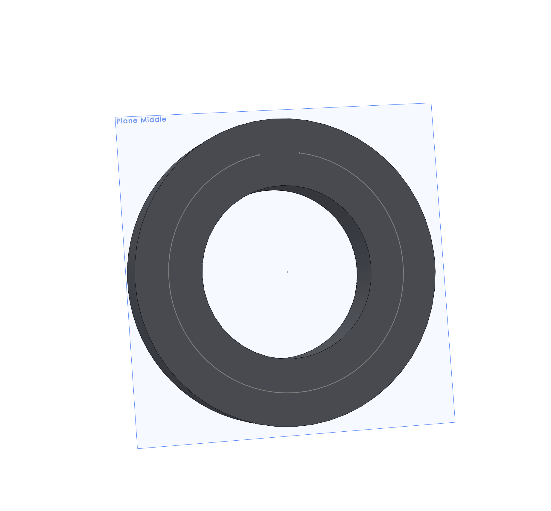
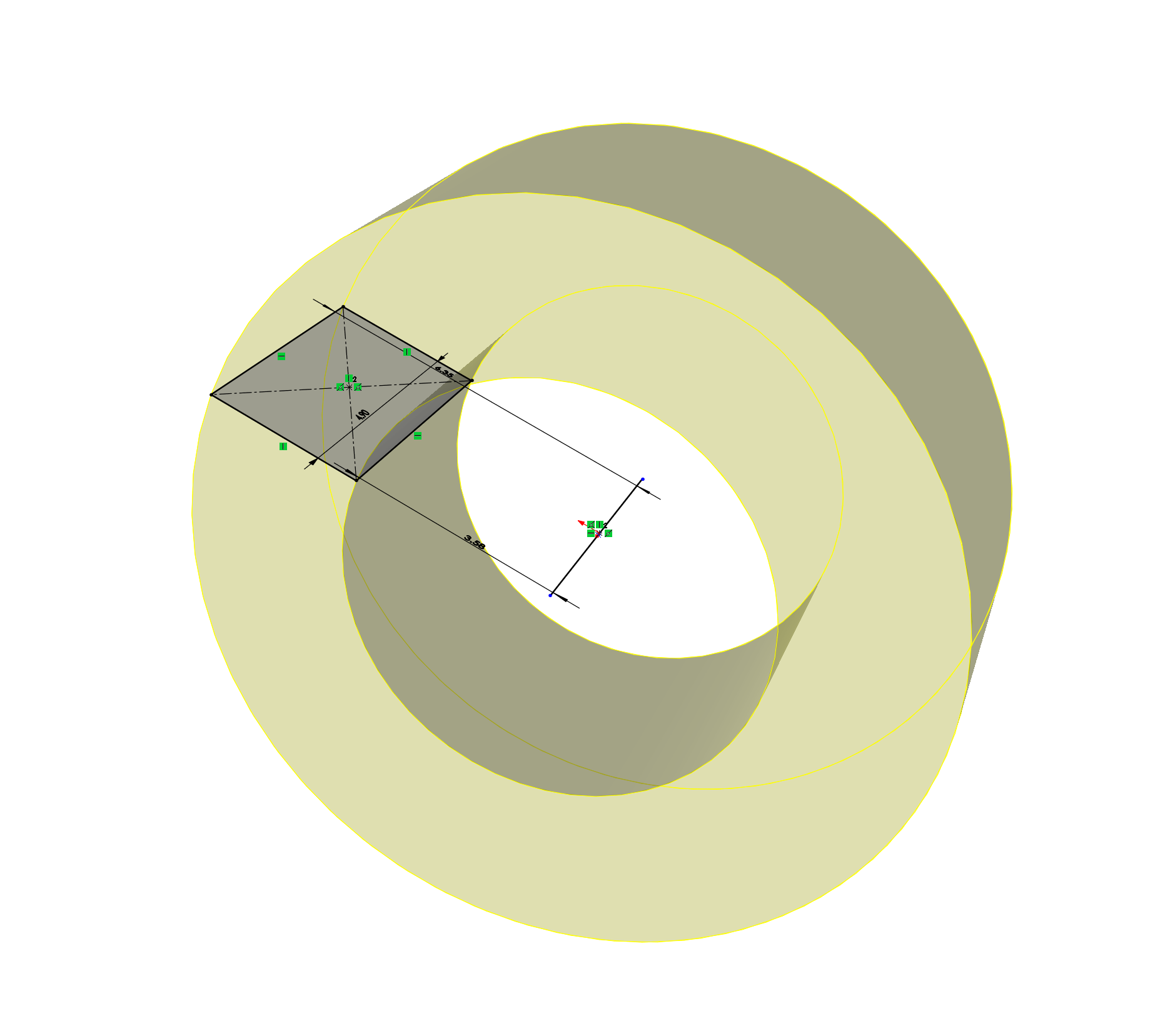
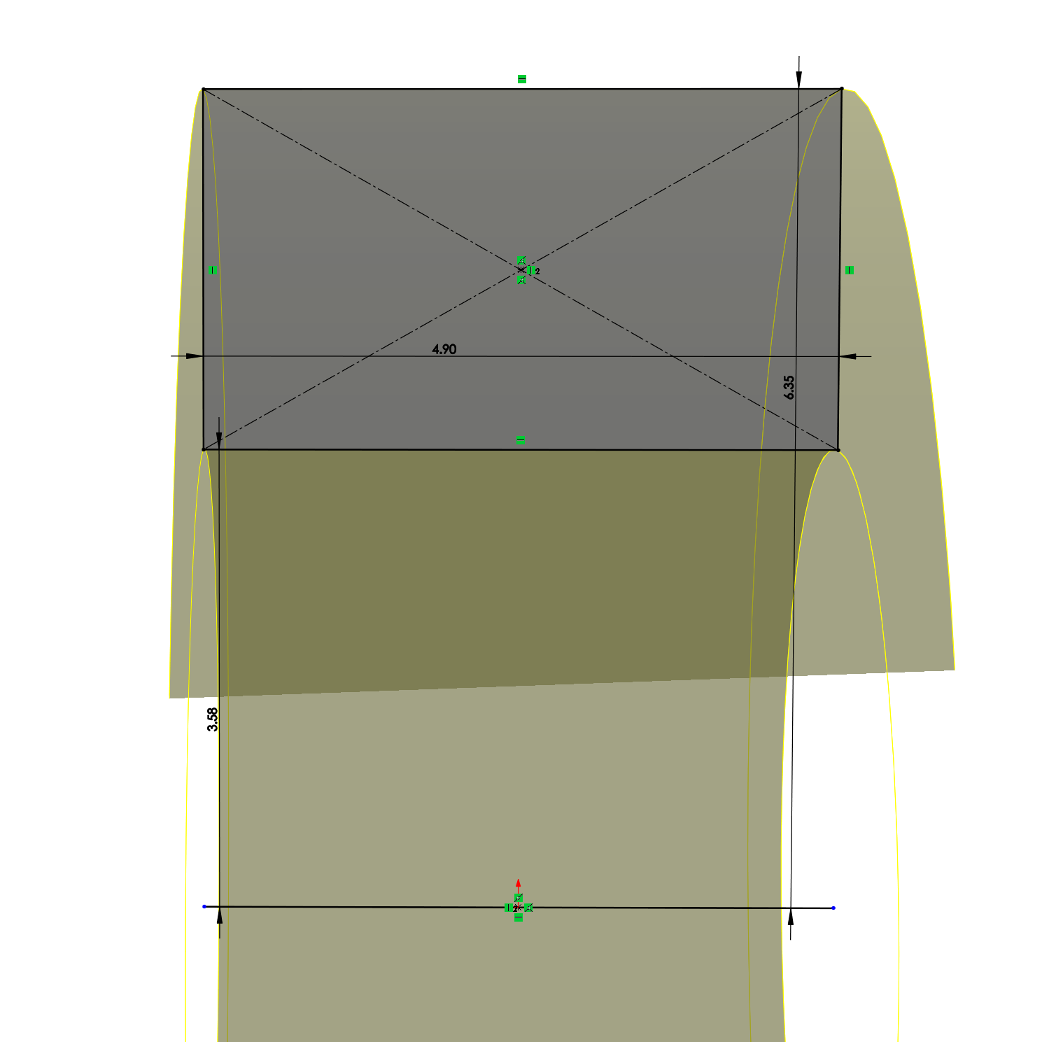
Create Surface Sweep Sketch
In this example the project method was used. Simple create a line around the center of the toroid where you want the wire to be wound around. Note that this is the start and end position of the wire.
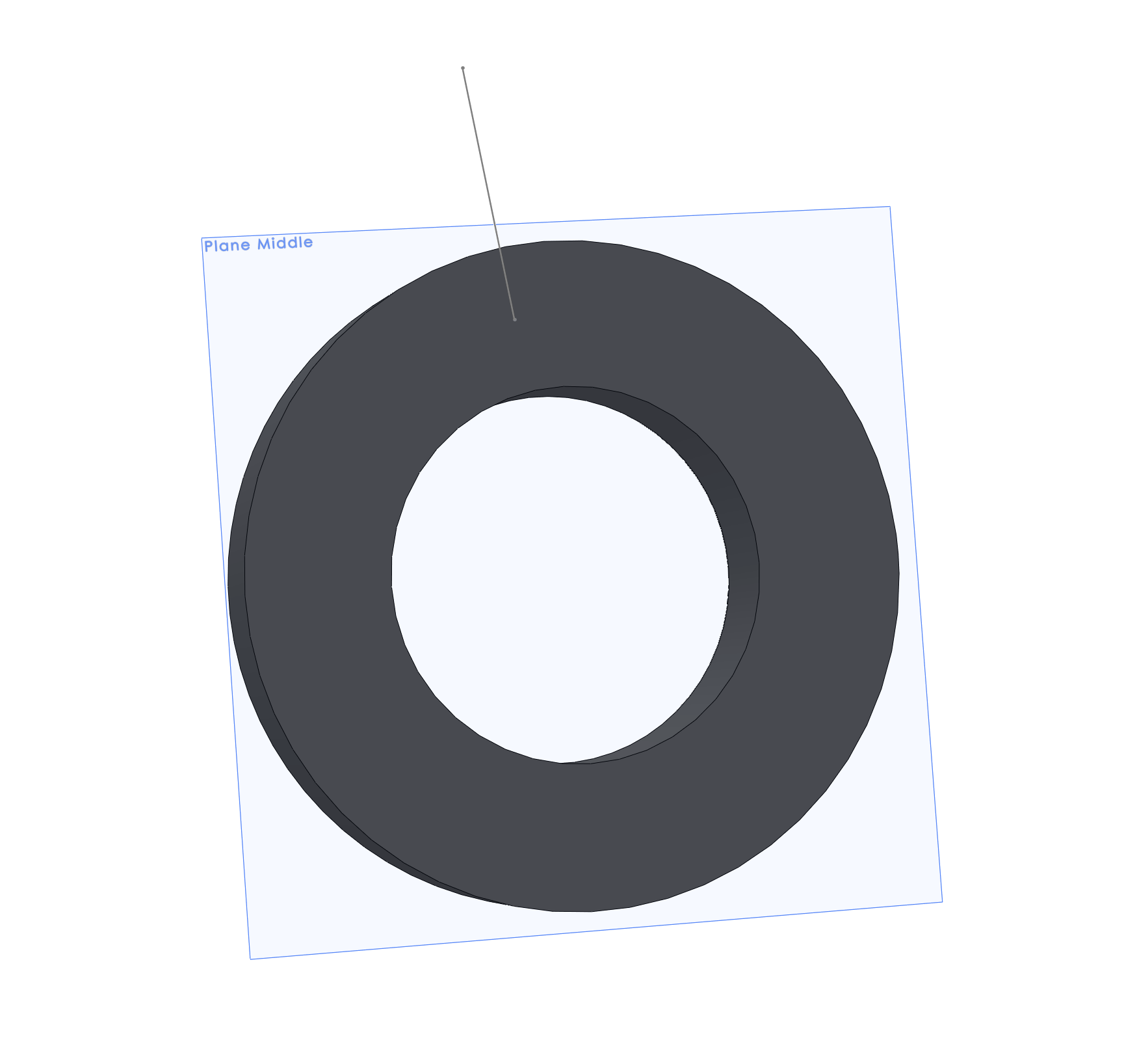
Next, create another sketch and add a single line (“profile line”) that is perpendicular to the starting position of the coil path curve. The exact length of this line is not important, however, it must be long enough such that when wound it will cross the largest radial distance but not be too long such that it intersects the opposite end of the toroid.
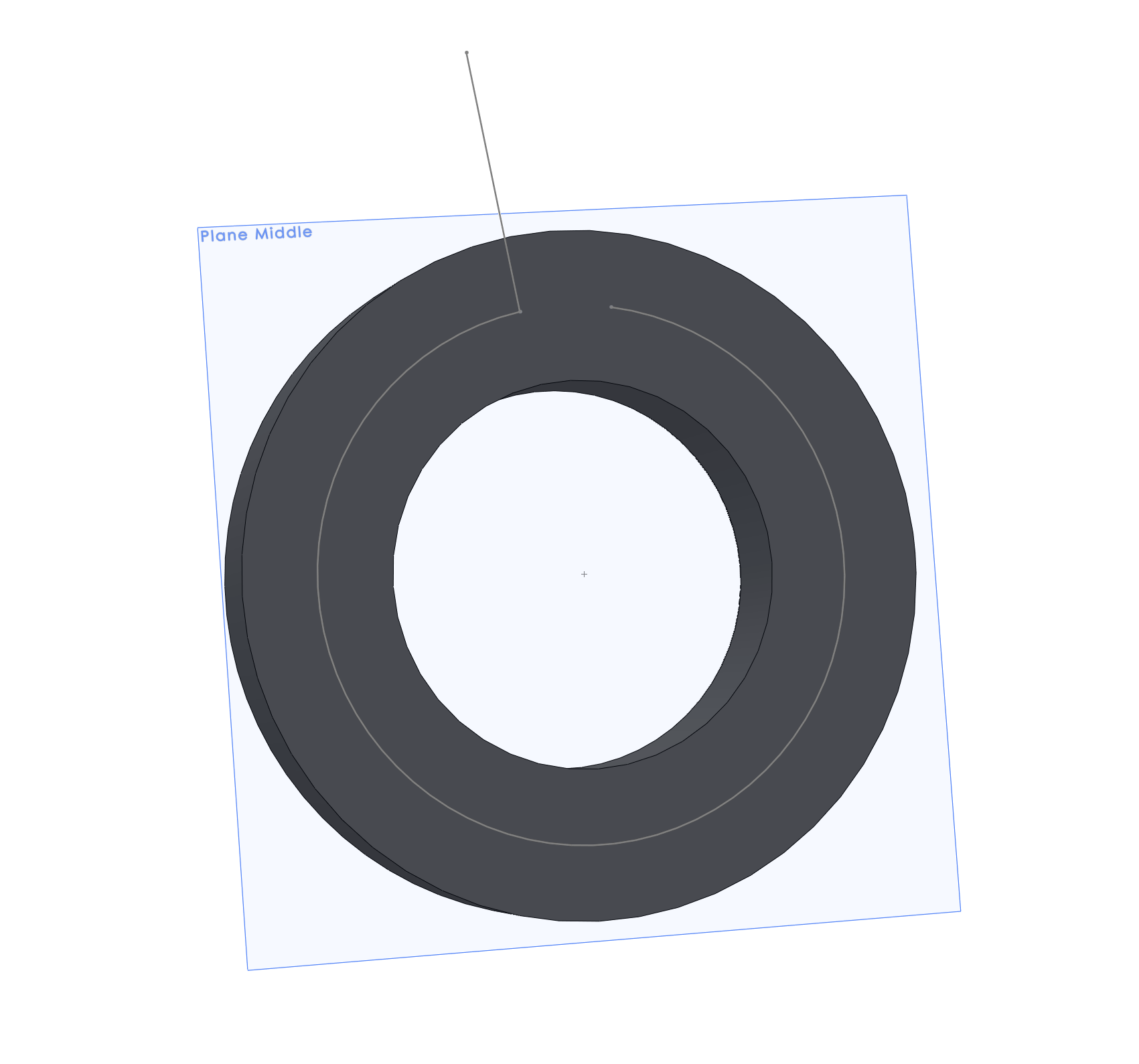
If you did this correctly the resultant geometry should be something like this. Note that these are two separate sketches.
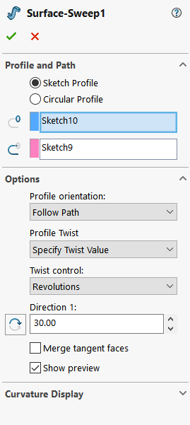
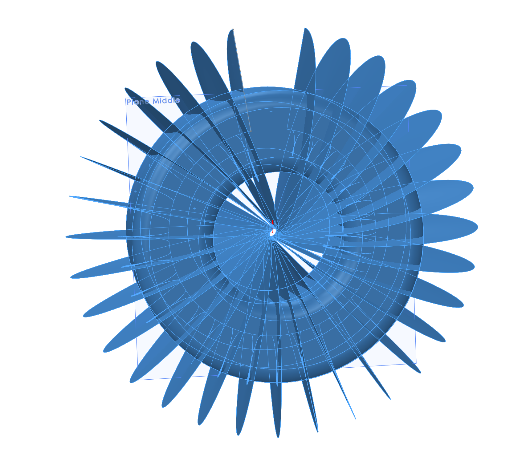
Using the Surface Sweep command select the perpendicular (“profile”) line for the profile. Then select the central arc for the path. Under options choose follow path, and then specify twist value using the revolutions for twist control. Then you can select the number of revolutions you want to have. In this example 30 turns were used.
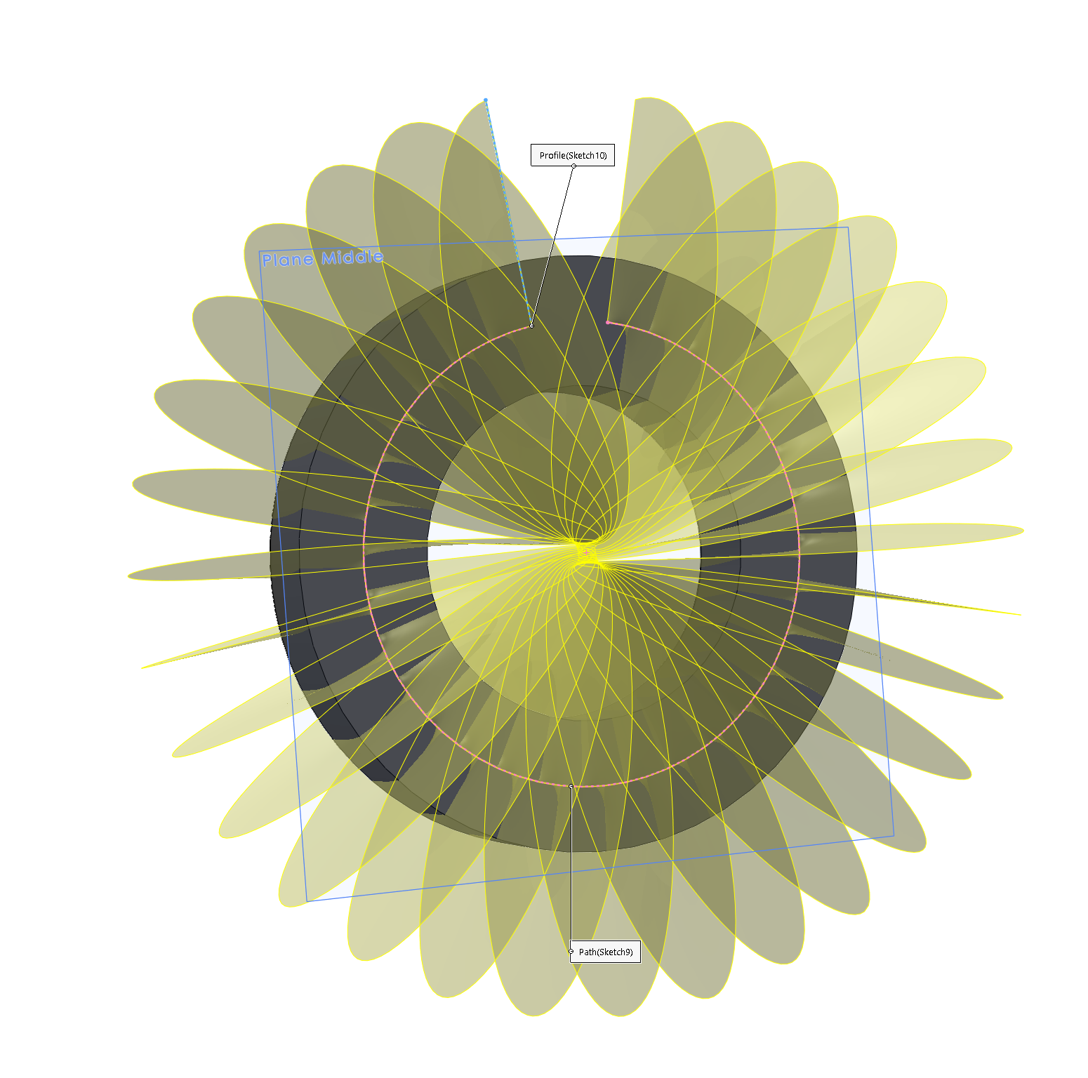
If you did everything correctly you should end up with something that looks like this
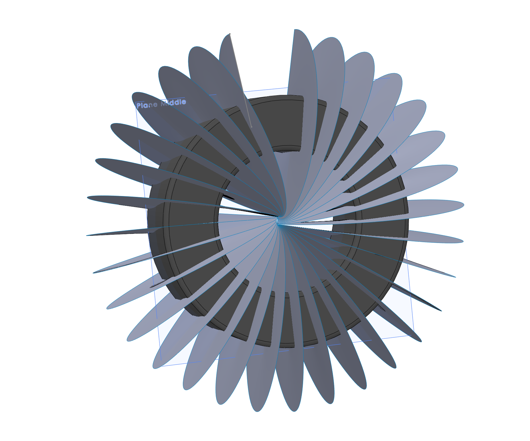
This is the resultant created geometry. Note that the offset surface is hidden for better clarity. We will then enable it for the following steps.
Intersection Curve
Now that the offset surface has been shown we can create our winding path. We do this using the intersection command.
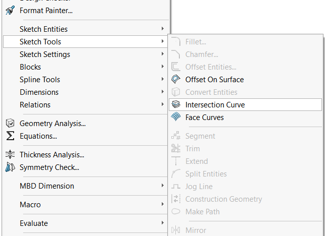
This can be found in the Tools menu under Tools > Sketch Tools > Intersection Curve.
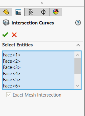
To use this simply select all of the faces of the offset toroid and the generated surface curve.
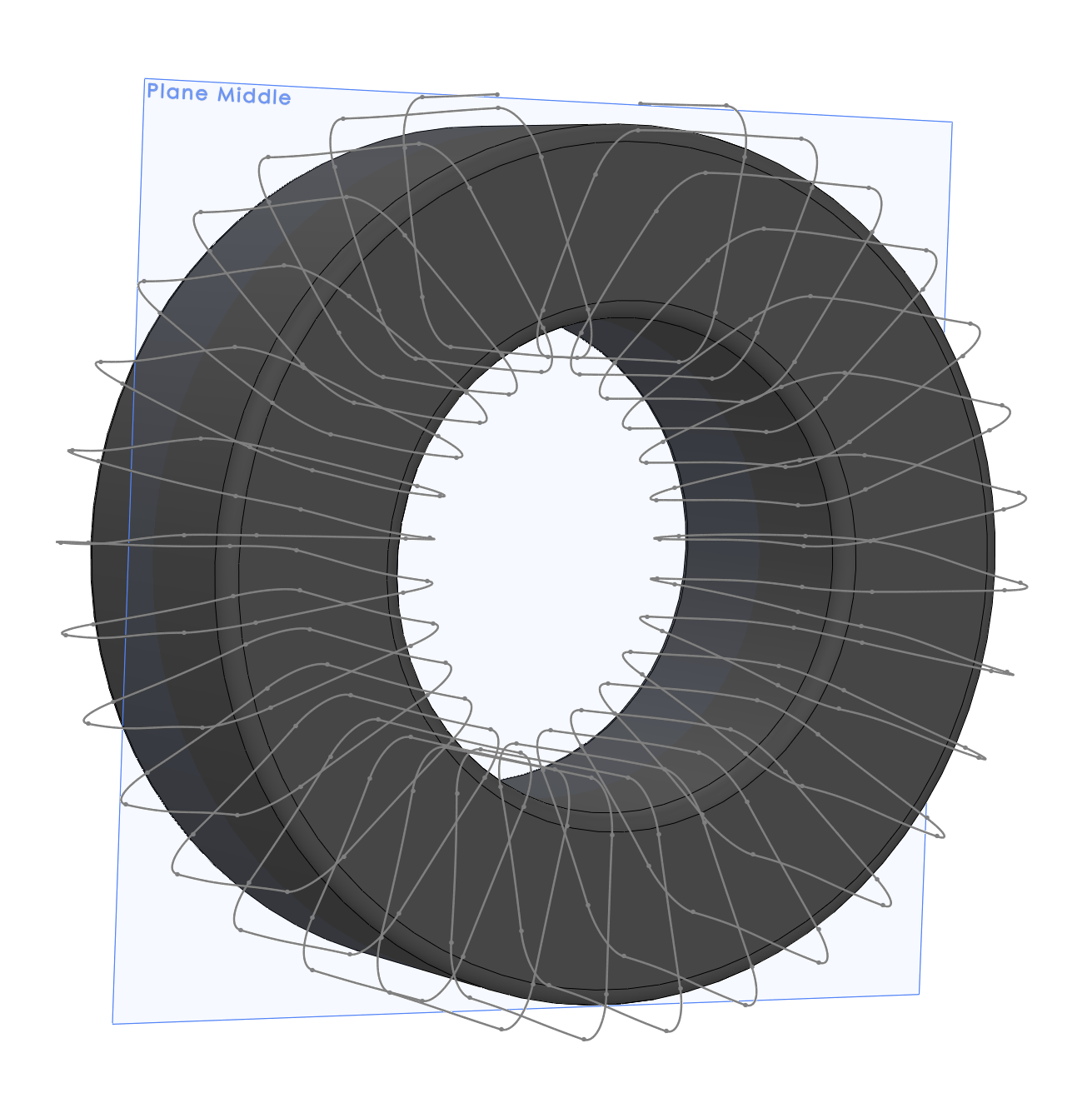
With the offset surface and other surface profiles now hidden this is the resultant curve that is generated.
Note
If your curve does not properly intersect and form a continuous path like this example try making the perpendicular (“profile”) line longer and repeating the process.
Creating the Wire
After the path has been created the sweep profile must be created. To do this, create a sketch perpendicular to one of the end points of the 3D path.
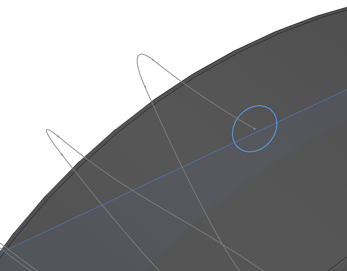
Then the sweep command can be used to create the final profile.
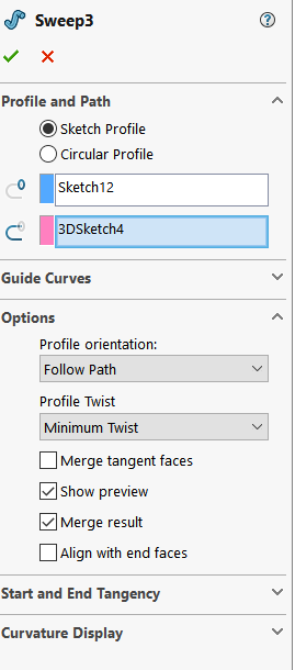
The sweep command can be found in the features tab. Simply select the profile sketch and the 3D path.
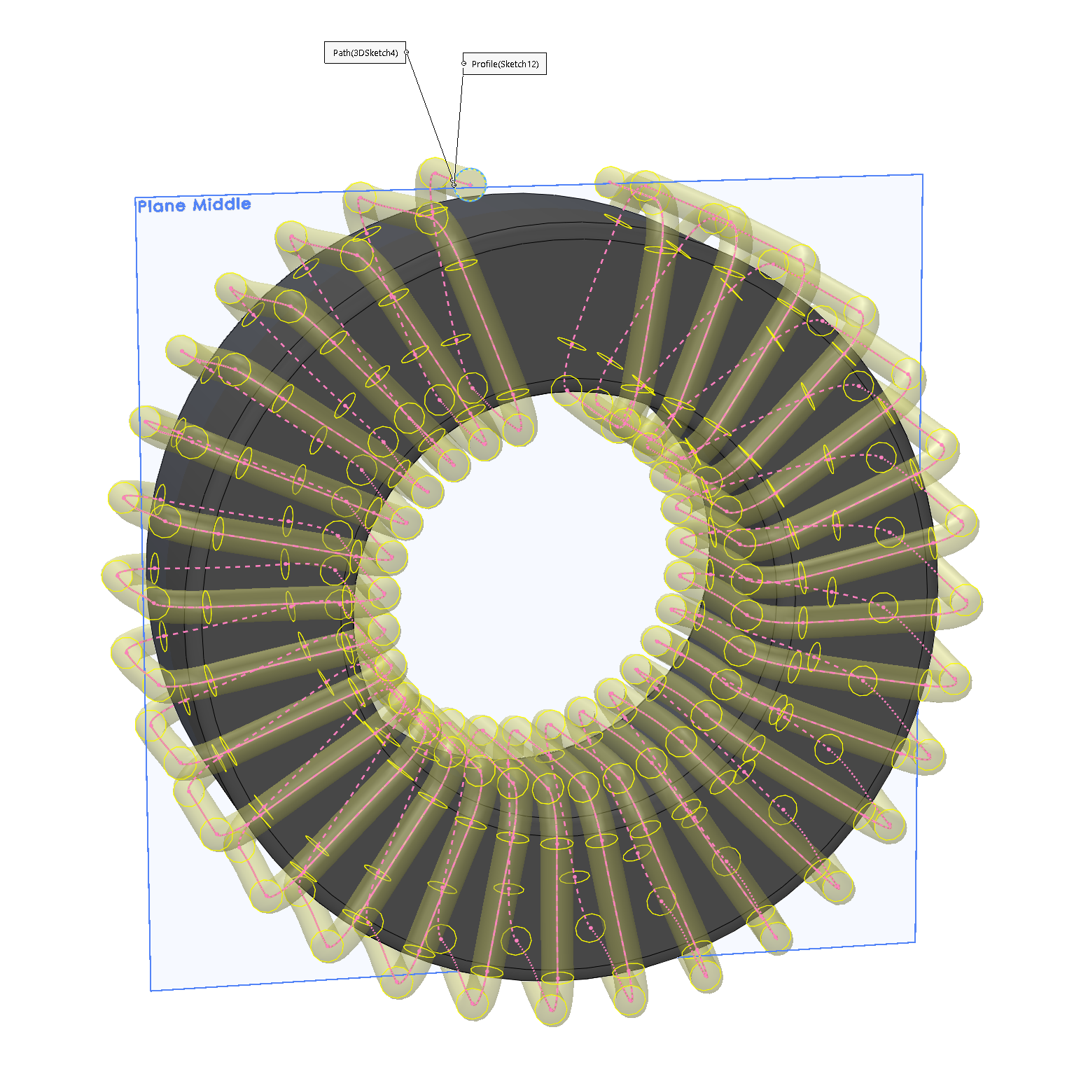
The preview, if done correctly, should look something like this.
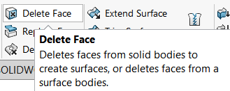
The result of the sweep leaves you with wire ends that need to be trimmed. This will be done using the delete face tool.
Note
If the gap between the conductor and the toroid is too large reduce the offset distance in the offset surface feature. You will not need to redo any of the steps as it will simply do this automatically if the steps were followed correctly.
Trimming the Winding
Once the toroid winding has been created there will be the leads that need to be adjusted. There are a few ways we can fix this but the easiest is simply to use the Delete Face tool in the Surfaces tab.
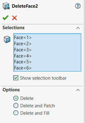
Select the first segment and bend of each side such that the winding is then opening straight.
The resultant geometry will now have two open ended winding that can be adjusted to have a standard straight wire length coming from them. There are a few methods that can be used. We can again use a sweep profile and some curves if we want them to be in the exactly parallel, or in this case simple extending them is good enough for this application.
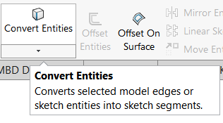
Simply create a new plane perpendicular to the wire end, then create a sketch on the end of each leg, use the convert entities tool and then extrude the surface to the desired length.
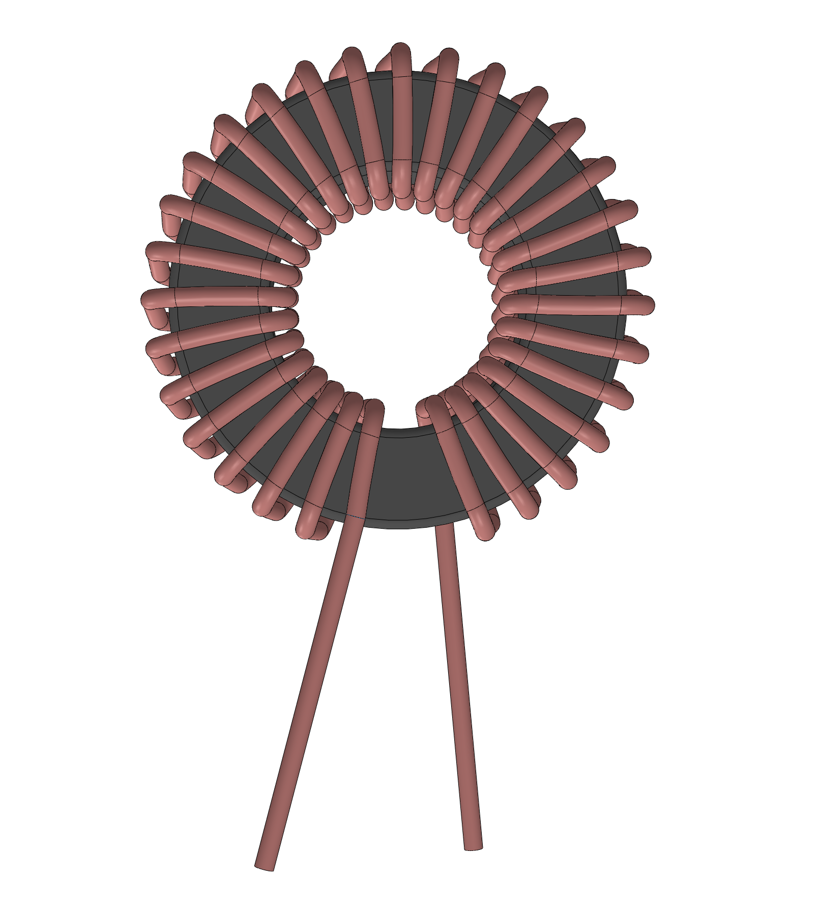
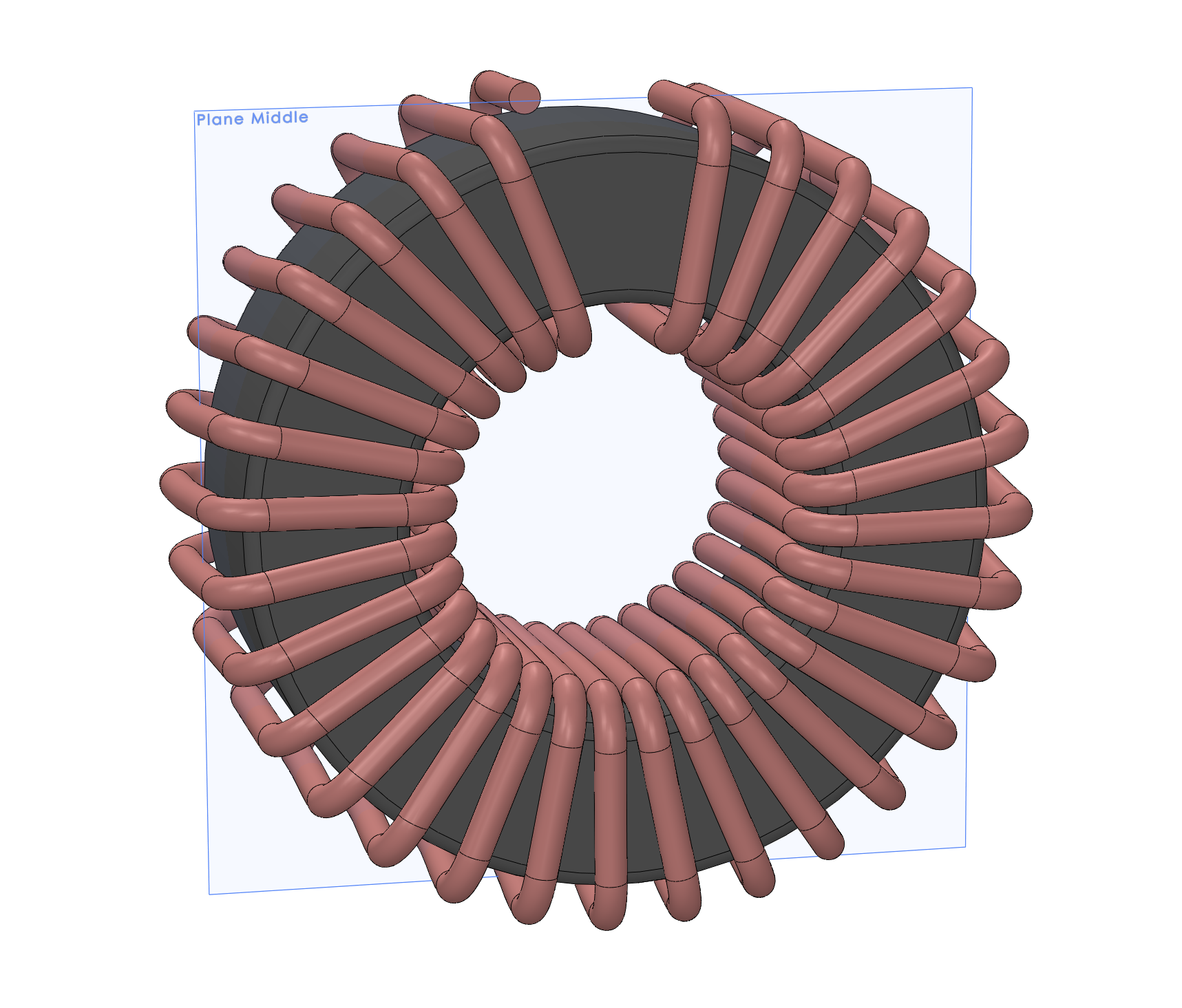
Resulting Wound Toroid
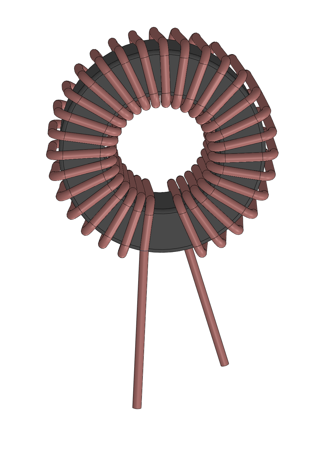
You should now see your completed and wound toroid!