RTD Simulation
Overview
In this article we discuss the development of a static resistance simulator for use in functional testing.
Table of Contents
Background
In test and measurement, you will often need reference standards. A reference standard in this context is a device that has a precisely known value. In other words, a known uncertainty. This can then be used as a transfer calibration standard when another device such as a device under test (“DUT”) is compared to the reference standard.
For this particular application a known resistance value was needed to simulate an RTD for a control system. This particular RTD simulator has three resistance values which could, in theory, be used to simulate up to 8 different discrete resistance values in additional to fault conditions
Features
This system features:
-
Fault simulation (Open, Short).
-
Smart Calibration via an EEPROM.
-
Multi-configuration capable (2, 3, and 4-wire) RTD simulation
-
Designed for replaceability.
-
Resistance configurable.
-
Power and condition indicators.
-
Front screw-in terminal block for easy wiring.
-
In-circuit calibration capability.
-
Long lifetime reed-relays.
Fault Conditions
When performing functional testing on a system it is important to consider fault conditions as well as operational parameters. Testing these fault conditions allows one to ensure that the system is able to detect the fault or act upon a fault since a fault typically means there is something wrong with the system and the measurements would be invalid.
Within this system there are two faults that are simulated. Those faults are open circuit, and short circuit. These fault conditions could have multiple root causes. For instance, a faulty (or burned out) sensor, manufacturing error such as miswiring, and so on.
Each of these fault conditions may present differently to a system. An open circuit may make the resistance appear much larger (RTD temperature hotter), and a short circuit much smaller (RTD temperature colder).
Performing these tests allows one to verify that the control system is able to detect, and potentially take corrective action to address these errors such as in systems with redundancy, or error detection to track transient occurrences.
Open and Short Circuit Faults
A resistance is typically measured by passing a known current through a circuit. A voltage drop will then occur across the circuit proportional to the resistance. When an open circuit is presented to the system there is nowhere for the current to flow. Typically, the excitation circuit will then transition to its compliance voltage which is the maximum voltage the current source can produce in an attempt to source the set current.
From there depending on how the sense leads are connected and where the break in the circuit is it can either be approximately 0V, or the compliance voltage. There are several ways to detect open circuits such as current monitoring, thresholds, and so forth but we are only concerned with simulation of such events for this project.
The actual application of open circuit fault testing allows the system to be characterized as well as test for faults that could occur in the control system hardware or software. For example, a system that should be capable of detecting and alerting to a fault through telemetry.
Fault Implementation
The way these faults are implemented in this system are with relays. These relays can be programmed and toggled at any point to generate a fault.
Component Selection
Reed Relays
Relays form the basis of this circuit. They are a critical component in that they are within the signal path. They contribute to the stability, and ultimate accuracy of the system. Given that long lifetime is desirable a reed relay was chosen. More specifically, a surface mount, form A relay, was chosen.
First off, reed relays are known for a long lifetime compared to traditional electromechanical relays typically hundreds of millions of actuation cycles. They are also typically smaller, lending itself well to a high-density channelized design. Reed relays are typically only found in low level signal switching applications though such as this. You would typically not want to use them to switch large currents due to the contact construction however switching the few milliamps in this application is no problem.
Next, the contact form is important. There are several types of contact forms but two major types are form A, and form C relays. A form A relay is a normally open, single pole, single throw design. In contrast a form C relay is a single pole, double throw design. There are also normally closed single pole single throw relays which would be a “form B” design.
One important thing to know is that there is a tradeoff when using a form C relay. Due to the design of these relay types, they can suffer from lower actuation lifetime, and a higher contact resistance. For example, the lifetime of a Form C could be 100M cycles whereas the Form A could be 500M cycles. A big difference that must be considered.
These are all reasons why this design chose surface mount Form A reed relays. They have a long life, small form factor, and low contact resistance supporting a high accuracy design with an extended service life.
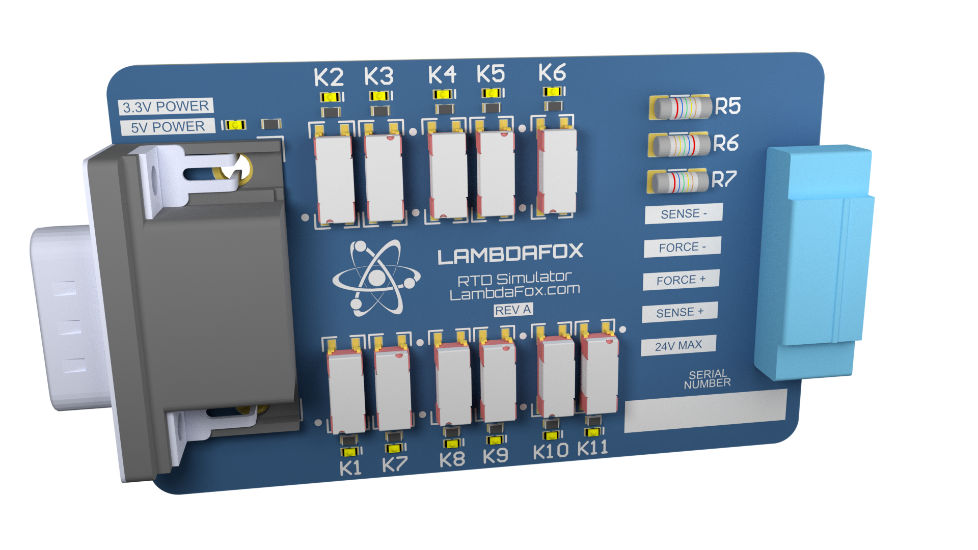
Connectors
The connectors in this design were selected to fit within the circuit board dimensions and not be so large such that they impact the ultimate mechanical packaging. Calibration must also be considered so using proprietary connector were avoided.
For the backplane connector a high-density D-sub connector was chosen because they are relatively inexpensive, rugged, and have both cable to board, cable to cable, and board to board options. This means that a calibration cable can quickly be made to support individual board testing as well as allowing remote control of the device.
The front panel connector was chosen to support field wiring of the connection using a screw mounted terminal block. This allows the connection to the resistive element to be independent from the logic connection minimizing crosstalk.
Drive Circuitry
The driver selected for this system is a packaged transistor array that incorporated kickback diodes. This means that discrete diodes do not need to be added to the relay coils to minimize back EMF.
Theory of Operation
Architecture
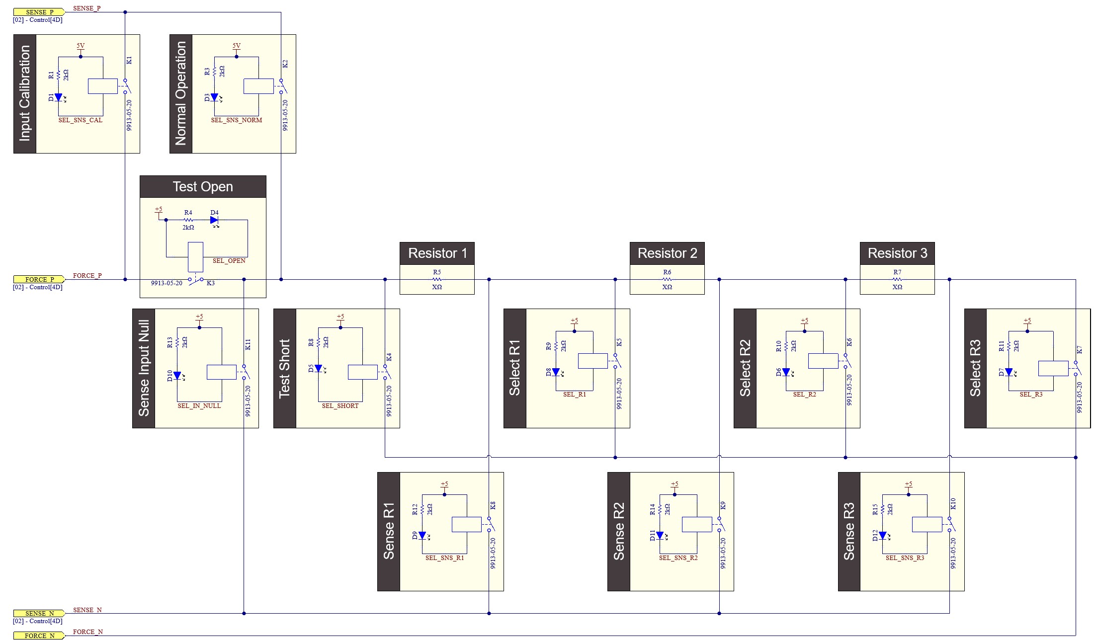 The architecture of this simulator is a series topology with switched sense lines. This architecture minimizes the relay pathways needed to interface with a resistor and is based on a resistance decade box architecture. Additionally, the series architecture minimizes the jitter and improves the stability of the load presented to the system. For example, the control could toggle the next resistor in make before break fashion to avoid a short or open circuit condition.
Input Calibration
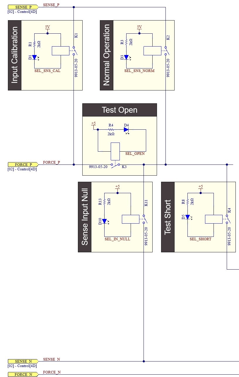
The input calibration relay is to facilitate measuring the test open relay to minimize uncertainty of the system as well as to serve as an indicator of remaining relay lifetime.
To measure the “Test Open” relay all relays would be open except for Input Calibration, Test Short, and Test Open. Excitation would then be applied to Force P and Force N. Sense P and Sense N would then be the measurement ports allowing to get a precise measurement of the contact resistance across test open.
This allows us to remove approximately 1% of uncertainty when measuring a PT100 RTD at the lower end of the measurement range and can be measured prior to each test where short term stability is a concern.
$$\Large 0.81\% = \frac{0.15e-3 \Omega}{18.52 \Omega}$$
Test Open
The test open relay allows an operator to simulate an open circuit condition. When used in conjunction with the Input Calibration as well as the Normal operation relays one can simulate multiple simultaneous faults such as an open sense line in both open and closed-circuit conditions.
Typical Operation
The typical operation of the circuit would be operating the sense and select relays. The select relays select which resistance is being presented to the system. The resistive elements are summed in this architecture, however, with the addition of bypass relays one could incorporate 8 discrete steps to present to the system.
EEPROM
This circuit also features a 1-wire EEPROM for storing calibration data for each channel. It is best practice to avoid hard coding parameters such as calibration values in software and instead aim for a modular approach. If one had to change a channel card out for any reason the calibration could be performed independently then read by the system prior to use. It also means that the card can be sent to a calibration lab as a standalone device instead of requiring the entire system to be shut down for calibration, potentially interrupting production.
LED Indication
LEDs have been added to each relay as well as the power rails. This is so that one can quickly debug and troubleshoot system problems such as loss of power, bad connections, or software logic.