Overview
In this article we discuss the design of a digital isolator with parasitically powered inputs.
Table of Contents
- Background
- Applications and Architectures
- Design Elements
- Component Selection Notes
- Custom Digital Isolators
Background
Digital isolators are used to keep signal return paths isolated from one another as well as protect the input to sensitive devices. They can also be used to shift logic levels such as 24V to 5V.
In this project we review the implementation of a high reliability digital isolator in a miniature package.
Features

This system features:
- Parasitically powered inputs.
- Easily replaced - Designed for quick connection and replacement.
- Configurable for logic levels up to 60V.
- 3000V Isolation barrier.
- Channel indicators
- SWaP Optimized - Lightweight and High Density.
Applications and Architectures
Digital isolators are used extensively in the control systems industry to isolate, protect, and level shift signals. They can be used to prevent ground loops which happen when a potential difference occurs between two returns or grounds. When a ground loop or potential difference occurs it can cause signal noise, jitter, and even equipment damage depending on the severity.
Digital isolators can even be used to protect against ground faults and short circuits. Take for instance when a cable gets chafed to the point that conductors become exposed which then shorts some voltage input to another signal. If all the signals were connected together to a common ground this could cause extensive system wide damage. Using a digital isolator can protect against this by isolating each signal to its own exclusive input.
There are a number of different architectures such as optical, inductive, and capacitive elements. This design uses a capacitive isolation technology due to the reliability it provides. Within this circuit is a silicon dioxide barrier which a modulated signal passes is able to pass through. The advantage to this particular type of isolation architecture is that is does not degrade over time, and features a substantially lower failure rate.
Optical Isolation Comparison
Opto-isolators are probably one of the most widely used forms of isolation. You will find them in everything from power supplies to even analog signal isolators. They work primarily by shining light on to a photo-sensitive element which drives a transistor (could be FET, BJT, SSR, etc).
The disadvantage in this architecture is that the light emitting element, typically emitting in infrared, degrades over time. Additionally these components degrade quickly in a radiation environments.
When designing with optical isolation there can also be challenges to ensure that part tolerance is sufficiently controlled for your application. Take for example the TCMT4106 where the output is a BJT. One of the key parameters is CTR or current transfer ratio. That is the ratio between the input current to the output current. These can be very wide even within a single batch. In order to ensure you have adequate and repeatable device performance one must incorporate the entire range into the design and potentially screen and test parts.
Design Elements
Channel Status Indication
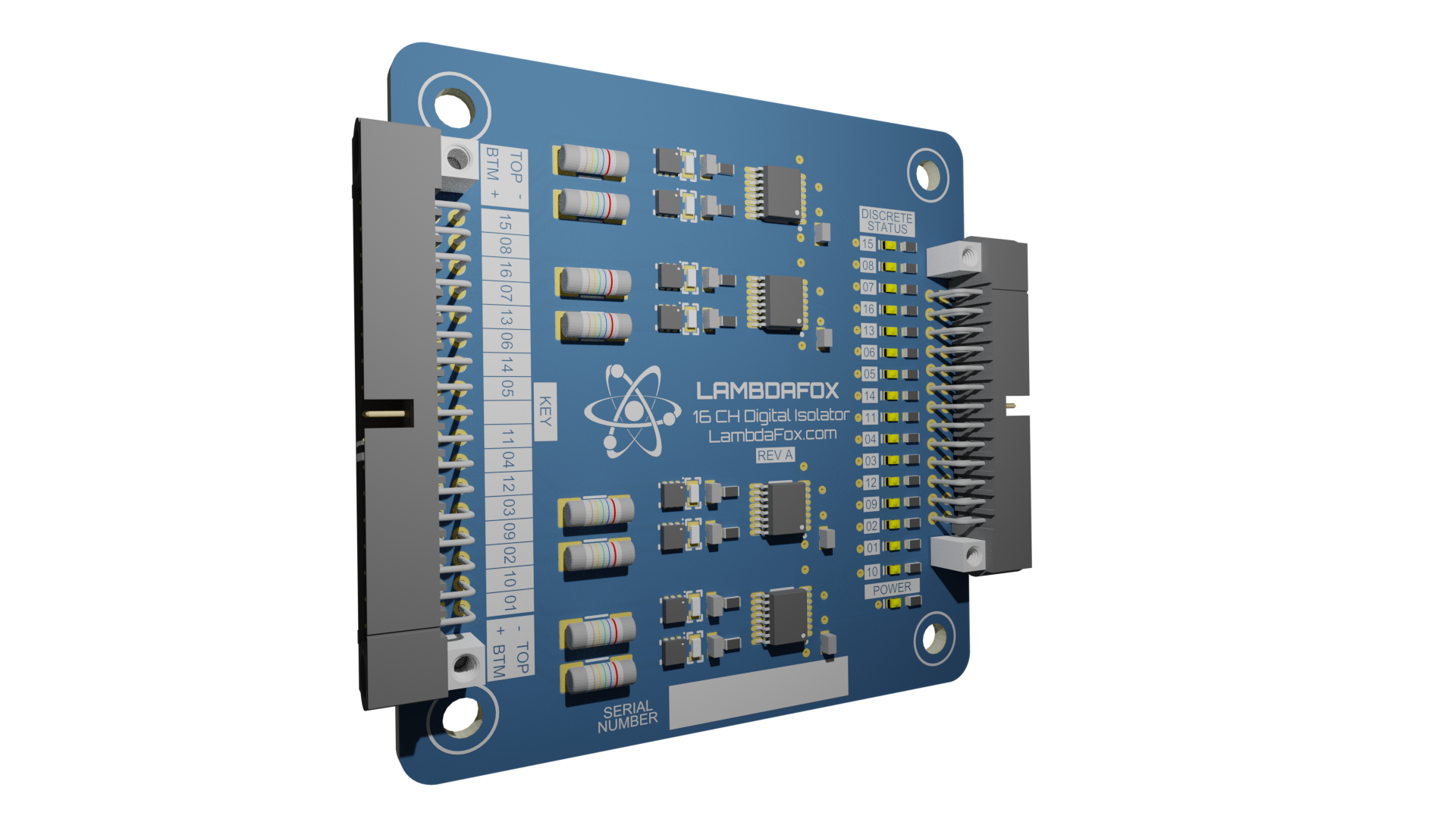
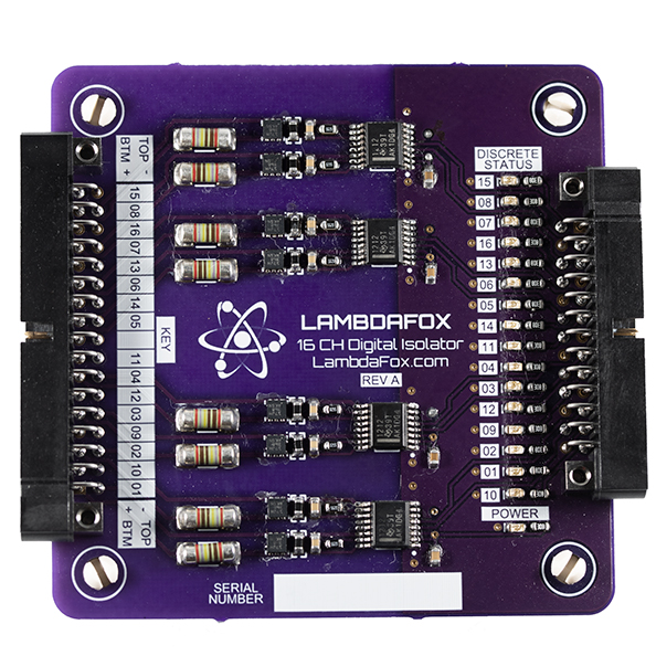
One thing I recommend adding to designs is indicators. For this digital isolator both power input as well as discrete status indicators were added. This allows the operator to see in real-time what a signal is doing without having to bring up software.
If you think about this carefully you will remember that these LEDs could also be a failure point. For each component added you potentially increase your statistical probability of failure. This design considered this carefully. The resistors selected for the current limiting ensure that even if the LEDs fail shorted that it does not allow the output of the digital isolator to substantially degrade or become unable to actuate the output.
I see a lot of engineers try to drive an LED at the maximum current, say 20mA. They light up with more than enough “oomph” at lower currents. Just a milliamp or two is more than sufficient to have an indicator that is visible in daylight.
Test Points
While I typically do like to see both inputs and outputs broken out into test points this design chose to disregard this to save space. Instead a cable harness was made that can be used to test each and every input and output of the device. It’s a relatively simple design so test points are not necessarily needed in this design. If space was no object then adding them would not be a problem.
Silkscreen
Notice in this design that silkscreen is present to assist an operator in both wiring as well as identification of the channels. This was done with inverted silkscreen because it improved readability in this design. Make sure to take the time to ensure the spacing and alignment of the silkscreen is uniform and not all over the place. It only takes a few minutes and improves the aesthetics and readability substantially.
In addition to the basic wiring specifications I also like to include:
- Revision Information
- Blank region for serial number marking
- Website
- Logo
- Dimensions (hole size, spacing, etc)
- Electrical limitations - You don’t want your customers to have to hunt down documentation to install your device! Make it as easy as possible.
Component Selection Notes
Resistors
Resistors may seem like a fairly simple component with little difference between them, however, that is far from the truth. The resistors selected for this design are Metal Electrode Leadless Face (“MELF”). Aside from wanting to roll off the circuit board when being soldered they are wonderful to use for applications involving surge protection. This is because they have a much better thermal dissipation and surge rating compared to standard rectangular form film resistors.
Connectors
The connectors for this project are Harwin Datamate series. These are rated for high vibration and shock environments. I like these connectors because they screw down to the board and the cable harness side has options for potting which can help reliability. The downside to these are that they can be labor intensive to assemble but the advantages far outweigh this for critical applications.
Custom Digital Isolators
Need a custom digital isolator designed for your application? We have very fast turnaround time and can provide recommendations for not only capacitive isolator solutions but also optical solutions. We can provide full detailed engineering analysis and SPICE simulation for circuits as well.
Contact us today!