Overview
In this article we discuss measuring the force created by a current carrying conductor in a magnetic field.
Contents
Background

When a current passes through a conductor it creates a magnetic field. If you place this conductor within a magnetic field it will create a force that can be measured with a balance.
Note that if you reverse the direction of the current, the force will reverse. The maximum force will occur when the conductor is perpendicular to the magnetic field.
Equations
\[\Large F=I \cdot L \cdot B \cdot \sin(\theta)\]Where
- \(F\) is force in Newtons.
- \(I\) is current in Amperes.
- \(B\) is magnetic flux density in Teslas.
- \(L\) is wire length intersected by magnetic field in meters.
Note that the \(sin(\theta)\) term will be ignored since the wire is perpendicular to the magnet and \(sin(90 ^{\circ})\) is \(1\).
Equations are derived from reference texts.1
Setup
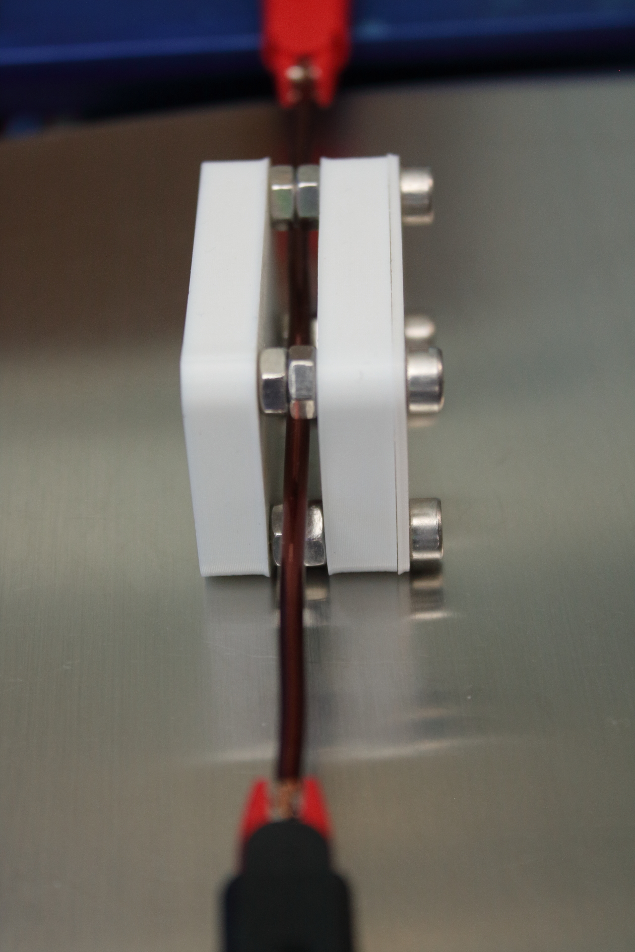
To measure the force a 3D printed magnet separator was created. This allows for an adjustable space between the magnets to be created. The screws used are only slightly magnetic stainless steel.
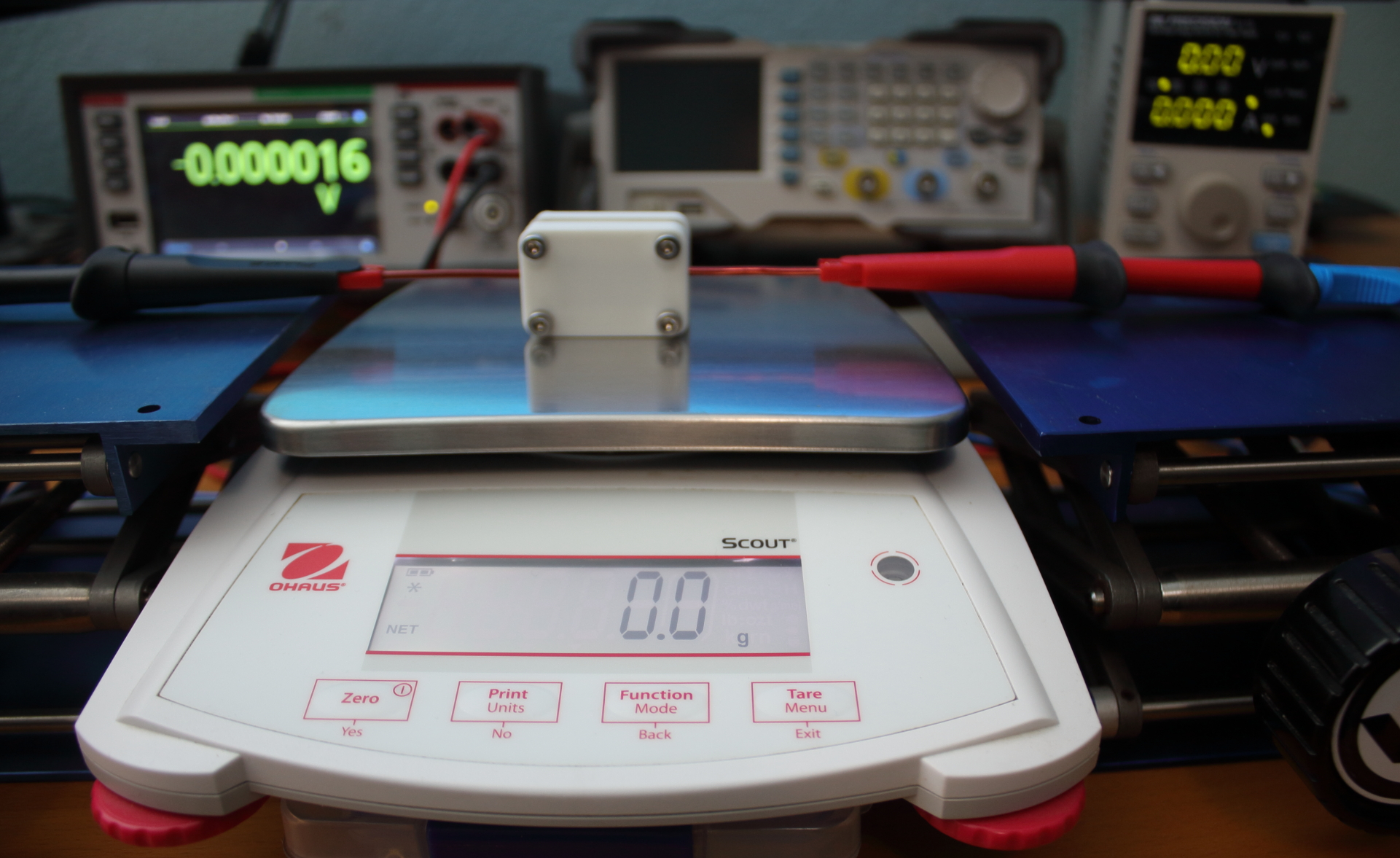
The magnet separator was placed on an Ohaus electronic balance. The conductor made of solid copper was then passed through the magnet separator in a manner that does not touch any surfaces of the scale or the holder. The leads to the power supply were then supported using two scissor lifts.
Once all equiment was setup the balance was tared to zero any applied force.
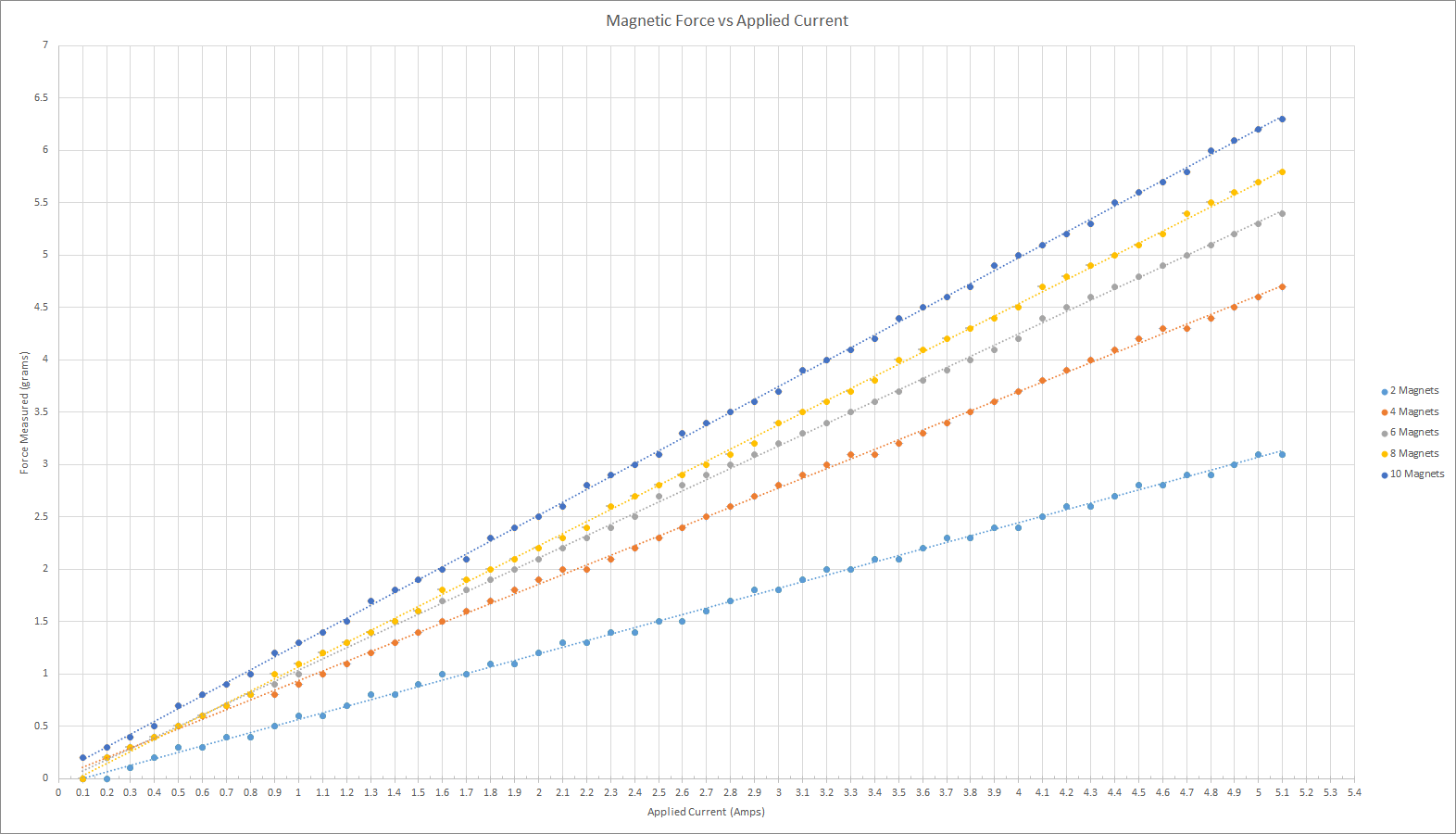
Measurements
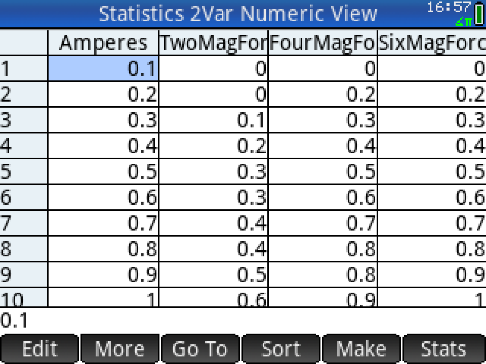
Measurements were taken in 100mA steps and logged manually using an HP Prime calculator in statistics mode. For each step the power supply was manually adjusted to the subsequent next step, and every 1A increment the power supply output was disabled to ensure the balance remained at zero applied force.
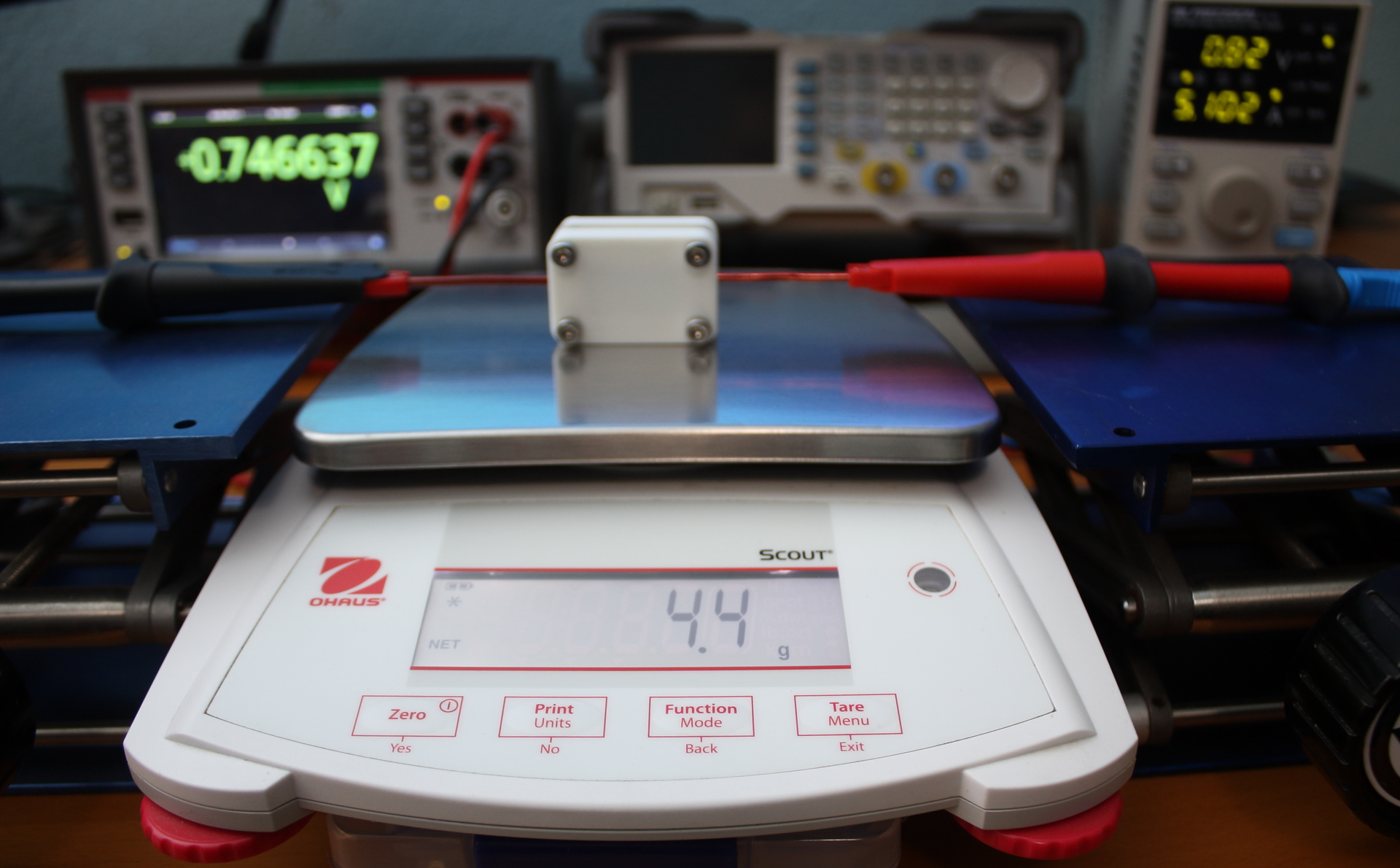
The maximum force with two magnets is pictured. The astute observer will note that the applied force is different than that collected during the plotted results. This is because the distance between the magnets was decreased therefore the magnetic field between the magnets is of larger magnitude.
The data was then transferred to a spreadsheet to generate a plot. Note that all calculations assume ideal conditions in that the magnetic force is even throughout the conductor intersection area.
The magnetic field can then be calculated. For the example provided in the photos the values are as follows:
Current: \(5.1\) amperes
Intersection Length: \(0.0254\) meters
Measured weight: \(4.4\) grams
\[\Large \frac{0.0044kg \cdot 9.81 \frac {m}{s^2}}{5.1 A \cdot 0.0254 m} = 332mT\]The tabulated data from the original experiment is as follows:
| Magnets | Calculated Field |
|---|---|
| \(2\) | \(234mT\) |
| \(4\) | \(355mT\) |
| \(6\) | \(397mT\) |
| \(8\) | \(417mT\) |
| \(10\) | \(494mT\) |
Final Notes
These results suggest that stacking magnets has diminishing returns in terms of increasing the magnetic field. A larger effect can be observed by simply decreasing the distance since the magnetic field drops off exponentially with distance.
The methods described are prone to setup induced errors and include many sources of potential inaccuracies. To measure a magnetic field in a laboratory setting one might use a field strength meter or a hall effect sensor which would likely provide a higher degree of accuracy. This method however is often used to demonstrate the force in a current carrying conductor to students.
References
-
Serway, R., Jewett, J. and Peroomian, V., 2018. Physics For Scientists And Engineers With Modern Physics. 10th ed. pp.755-757. ↩