Table of Contents
- Overview
- Motivations
- The Connector
- Serial Interface Discovery
- Serial Interface Connection
- Bill of Materials
- Additional Resources
Overview
The Ohaus Scout SPX is a portable electronic balance that has a peripheral interface connector. This connection supports many different proprietary peripherals such as printers, displays, ethernet, Bluetooth, and so on. Each of these peripherals use this same 6-position mini DIN connector. This article will discuss how this interface works and how to enable the serial port capability for just a few dollars worth of materials.
Motivations
This scale has been particularly useful to measure and quantify things, however, much of my research involves repetition or data analysis over time. It is highly labor intensive to manually record such measurements when a serial port already exists on the device. Additionally, it leads to an increasing degree of inaccuracy due to human error.
While these peripherals do already exist in a plug and play fashion I do not want to fork over several hundred dollars for a serial interface when I could simply build a cable and connect one of my existing serial interface devices. Additionally, I want to share my findings so that others may also be equipped to build similar devices.
The Connector
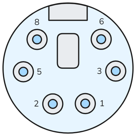
Note
The connector pinout pictured is as viewed from the back of the Ohaus balance receptacle.
The connector on the Ohaus balance is a 6 position mini DIN connector. Several connectors were fitted, however, the one that worked best and was ultimately used was a Kycon KMDLAX-6P-KPPSR. This was about $5.80 from DigiKey time of purchase, however, cheaper versions are available that likely fit just as well.
Pinout
The connector pinout consists of a UART bus, an options detect, power enable, and power connections.
| Contact | Function |
|---|---|
| 1 | GND |
| 2 | VCC |
| 3 | RXD |
| 5 | TXD |
| 6 | Power Enable |
| 8 | Option Detect |
Cable Build
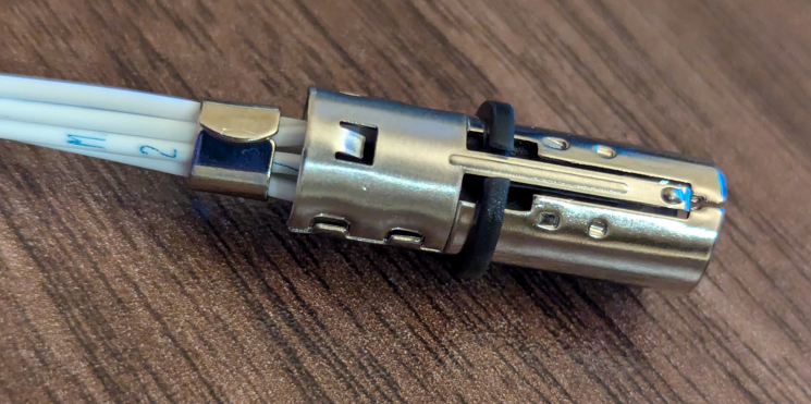
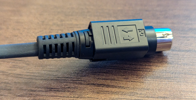
A cable was built using the Kycon connector. This is a solder cup connector so 6 wires approximately 1ft long were prepared and soldered to the connected then assembled and connected to the electronic balance for testing. Kycon has an assembly video for this connector on their website. The assembly was relatively straight forward and produced a nice cable.
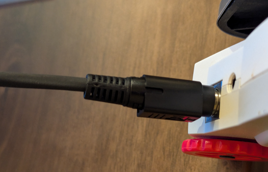
This cable was then test fit with the balance where it fit perfectly.
Option Detect
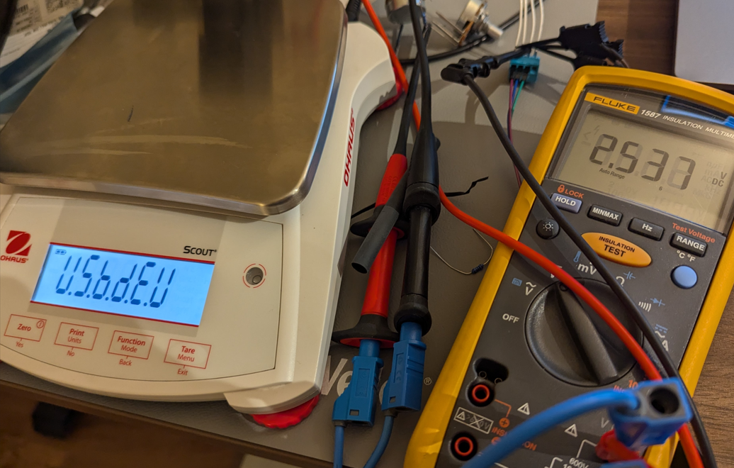
Based on experimental testing it appears that the option detect has a weak pull-up which detects what option is connected based on a voltage reading from the resistive divider formed by an external resistor connected between option detect (8) and GND (1). Connecting a potentiometer across option detect and GND allows the voltage at the node to be swept which reveals the available options.
When an option is found the scale presents a display message upon startup. In the case of Bluetooth the icon shows up immediately which suggests the scale is constantly checking for connected peripherals.
Once an option is found a display menu item then appears allowing system settings to be adjusted. Once USB device was found I then enabled the automatic print option.
Other options may exist since evaluation stopped once USB device option was found. The below table shows the options that were found.
| Option | Voltage |
|---|---|
| Display | 1.0V |
| Bluetooth | 1.458V to 1.789V |
| Ethernet | 1.836V to ~2V |
| USB Host | 2.144V to 2.404V |
| USB Device | 2.478V to 2.541V |
Serial Interface Discovery
While adjusting the options detect a logic analyzer was connected to the TXD and RXD pins to check for activity. After enabling the automatic print option, message traffic could be seen on the TXD pin. Since this is standard UART an FTDI cable can be used as a virtual COM port.
Screen captures of the message traffic from the logic analyzer can be seen below.


Serial Interface Connection
Now that the connection scheme is known an FTDI cable can be connected. The logic levels were not measured, however, VCC was about 5.5V, and both open detect and power enable were 3.3V. Logic levels are likely 3.3V, but could be 5V. Regardless the 3.3V FTDI cable was chosen since it is 5V logic tolerant and should function in both a 5V and 3.3V logic system. I recommend using a genuine FTDI brand cable but there are many other brands available for slightly less that are likely just as functional. The pinout and color combinations may differ.
Cable Connection
The exact cable used was the TTL-234X-3V3. Drivers for this specific cable can be found on FTDI’s website here. If the goal is to solder this to the connector directly then a wire end version can also be purchased.
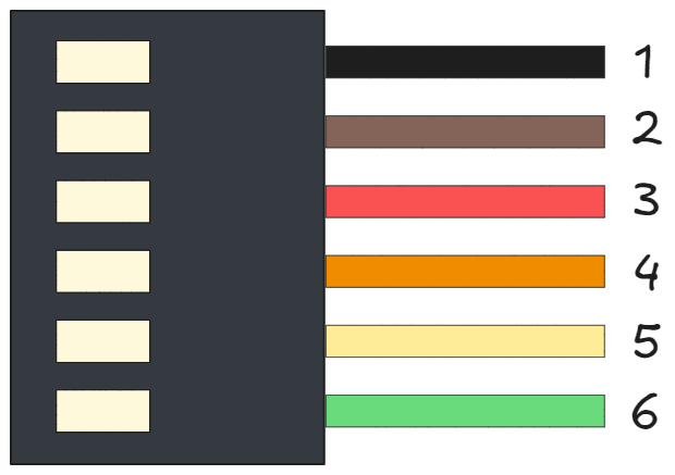
| FTDI Cable Contact | Color | Name | Ohaus SPX Connection |
|---|---|---|---|
| 1 | Black | GND | GND |
| 2 | Brown | CTS# | Not Connected |
| 3 | Red | VCC | Not Connected |
| 4 | Orange | TXD | RXD (Pin 3) |
| 5 | Yellow | RXD | TXD (Pin 5) |
| 6 | Green | RTS# | Not Connected |
Serial Output
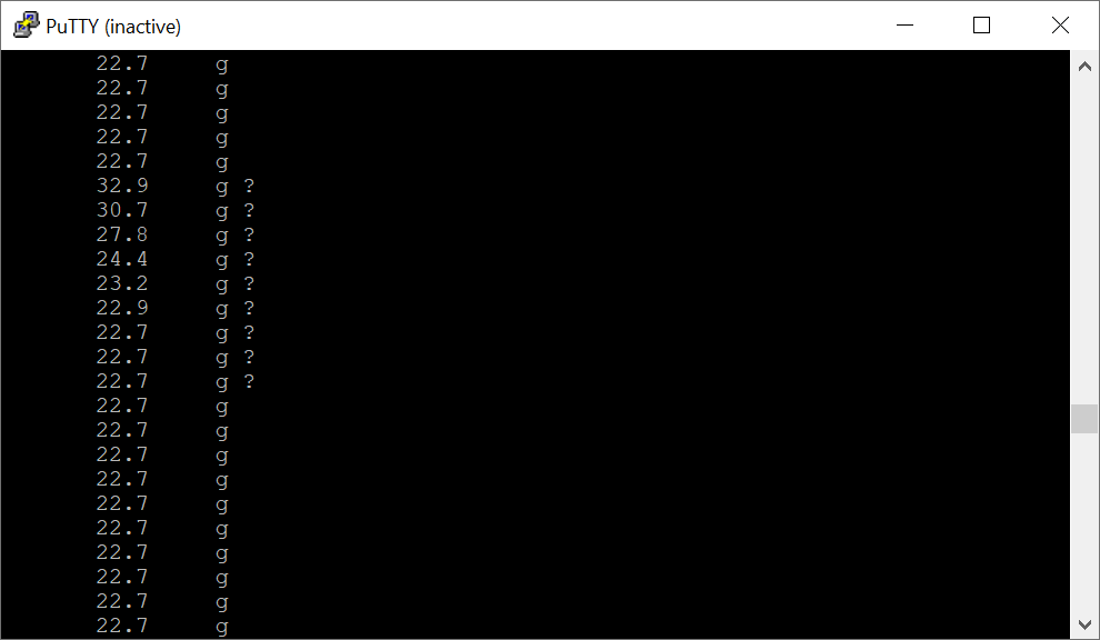
Since automatic print mode was enabled the balance will continuously output the measurement to UART which is then output by the FTDI cable as a COM port which can be read by the serial terminal on most operating systems (Windows, Linux, and Mac).
The output includes a question mark when the balance is changing. In the following example light pressure was applied to the balance to cause a shift in output.
Bill of Materials
The following is a list of all parts consumed in this cable build.
| Part | Manufacturer | Part Number | Approximate Cost | Purchase Link |
|---|---|---|---|---|
| Connector | Kycon | KMDLAX-6P-KPPSR | $5.80 | DigiKey - KMDLAX-6P-KPPSR |
| UART Cable | FTDI | TTL-234X-3V3 | $20.25 | DigiKey - TTL-234X-3V3 |
| Heatshrink Tubing | Qualtek | Q2-F-RK1-3/32-01-6IN-32 | $2.01 | Mouser - Q2-F-RK1-3/32-01-6IN-32 |
| Wire | Mil-Spec | M22759/11-22-9 | ~$2.00 | Wiremasters M22759/11-22-9 |
| Potentiometer | Generic | ~35k Resistor | <$1 | - |
The potentiometer used was an Alpha 25k in series with a 10k ohm resistor. The exact resistance was not measured. Instead the voltage at the node was tuned to the voltage described in the prior section.
Additional Resources
| Resource | Link |
|---|---|
| FTDI Drivers | FTDI - Virtual COM Port Drivers |
| Ohaus SPX Balance Product Page | Ohaus SPX Product Page |
| Ohaus Scout SPX Instruction Manual | Ohaus SPX Instruction Manual |
| Ohaus RS232 Interface Manual | Ohaus RS232 Instruction Manual |